CB-100-1
47
A
E (4x)
B
D
C
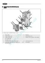
Fig. 8: Detailed view of the through-switch cabinet mounting (ex-
ample FDU)
A
Upper housing cover
B
Lower housing cover
C
Switch cabinet wall
D
Gasket (in the accessories kit)
E
Fixing screws
4.5
Mounting the fixtures for power connection cables
and control cables
The fixtures for the power connection cables and con-
trol cables are delivered as standard in the accessories
kit and must be mounted together with the ferrite core
or the ferrite cores (see figure 10, page 51) up to
VARIPACK housing size FJU+145, in order to achieve
the EMC class C2.
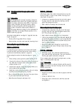
Graphical explanations, see figure 9, page 48.
Mounting the rear fixture for the power connection
cables:
• Remove the lower housing cover (see chapter
Through-switch cabinet mounting (option), page 43).
• Place the fixture from behind at the bottom on the
two fixing holes and insert the delivered screws from
the front and tighten them.
• Replace the lower housing cover.
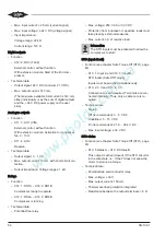
Mounting the front fixture for the control cable:
• Remove the control module cover (see chapter
Through-switch cabinet mounting (option), page 43).
• Unscrew the interface extension containing the real-
time clock. To do so, loosen the captive screw from
the interface extension and press the right and left
plastic clips towards the inside. This will open the
lock.
• Pull out the interface extension towards the front.
• Screw the fixture for the control cable into the now
visible right and left fixing holes from the front using
the enclosed screws.
• Replace the interface extension until the plastic clips
lock and tighten the captive screw.
• Screw down the control module cover again.
Summary of Contents for VARIPACK FDU+12
Page 12: ...CB 100 1 12 1 2 3 4 Abb 7 Steuremodul abmontieren...
Page 46: ...CB 100 1 46 1 2 3 4 Fig 7 Dismounting the control module...
Page 70: ...Notes...
Page 71: ...Notes...


