background image

Bird Site Analyzer

20

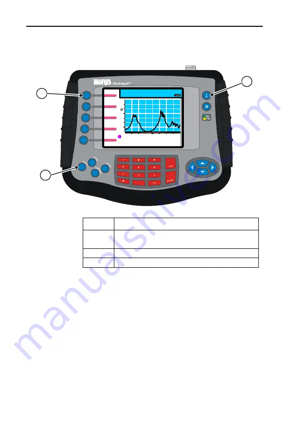
Figure 3 Selecting the Measure Match Mode

Setting the Measurement Frequency

You must be in the Measure Match mode to set a 
frequency.

Frequencies can be set manually or chosen from a list 
of presets (band list). If the start, stop, center, or span 
frequency is manually set, the band list will indicate 
“Custom”. Be sure to set the frequency to a value that 
is well beyond the normal range of the antenna. For 
example, for a 450 MHz antenna, set the start 
frequency at 400 and the stop frequency at 500 MHz, 
for an 800 MHz antenna, set the start frequency at 
700 and the stop frequency at 1,100 MHz.

1

2

3

800.00

MHz

1600.00

Calibration: OFF

Save/

Recall

Auto

Scale

Limit

Test OFF

HOLD

Print

10.00

1.00

V

S

W

R

 (0.00/ 

  )

Measure Match

[238 Pts]

Step

Action

1

Turn On the Site Analyzer. Press ON/
OFF key for ½ second.

2

Press the MODE key

3

Press the Measure Match key

Summary of Contents for SITE ANALYZER SA-1700EX

Page 1: ...FOR MODELS SA 1700EX SA 1700EXP SA 2500EX SA 6000EX Copyright 2006 by Bird Electronic Corporation Instruction Book Part Number 920 7002A600S Rev E Site Analyzer is a trademark of Bird Electronic Corpo...

Page 2: ...This page is not blank...

Page 3: ...ing Statements The following safety warnings appear in the text where there is danger to operating and maintenance personnel and are repeated here for emphasis WARNING Warning notes call attention to...

Page 4: ...isconnecting a sensor CAUTION When using a Bird 5011 or 5011 EF do not exceed 2 W average or 125 W peak power for 5 s Doing so will render the sensor inoperative CAUTION 22 dBm max input Do not apply...

Page 5: ...RUMENT IMPIEGO QUALORA QUESTO STRUMENTO VENISSE UTILIZZATO IN MODO DIVERSO DA COME SPECIFICATO DAL PRODUTTORE LA PROZIONE DI SICUREZZA POTREBBE VENIRNE COMPROMESSA SERVICE SERVICING INSTRUCTIONS ARE F...

Page 6: ...VENIR UN CHOC LECTRIQUE DANGEREUX NE PAS EFFECTUER D ENTRETIEN SI L ON N A PAS T QUALIFI POUR CE FAIRE ASSISTENZA TECNICA LE ISTRUZIONI RELATIVE ALL ASSISTENZA SONO PREVISTE ESCLUSIVAMENTE PER IL PER...

Page 7: ...make match measure ments as well as providing instructions for all functions available in Measure Match mode Fault Location Mode Lists the steps to make distance to fault measurements as well as provi...

Page 8: ...Bird Site Analyzer vi...

Page 9: ...vii...

Page 10: ...ower Up 9 Self Test 9 System Information 9 Site Analyzer User Keys 10 Site Analyzer Display Screen 13 Display Description 14 Chapter 2 Calibration 17 Calibration Accessories 17 Calibrating 17 Chapter...

Page 11: ...ation Mode 52 What You Need to Know About Setting the Frequency Span and Max Distance 53 Setting the Frequency Span 54 Setting the Maximum Distance 58 Calibrate the Site Analyzer 59 Setting the Cable...

Page 12: ...cription 114 Setting the Full Scale Power 115 Zeroing Bird Power Sensors 115 Choosing the Displayed Measurement 117 Setting Units 118 Changing the mode for the 5010B 118 The 43Peak Mode 119 Using the...

Page 13: ...nce 135 Troubleshooting 136 Battery Replacement 137 Firmware Update 138 Upgrade to Model SA6000EX 139 Customer Service 139 Service Facility 140 Sales Facilities 140 Specifications 140 General 143 Part...

Page 14: ...xii Markers 152 Run Hold 152 Equations 152 Fault Location 152 Resolution 152 Maximum Distance 152 Fault Location Distance Tables 152...

Page 15: ...A 2500EX 780 MHz 2500 MHz with power measurement capability SA 6000EX 25 MHz 6000 MHz with power mea surement capability Antenna systems are tested by using a Site Analyzer to measure match conditions...

Page 16: ...ied y Calibration Combination Cal Combo Site Analyzer Features General y Easy to operate and field ready for first time occasional and experienced users y Step by step guide shows how to make some of...

Page 17: ...default setting of 238 data points to facilitate conversion between Measure Match Sweep and Fault Location DTF y Measurement data can be transferred to the Anritsu Site Master Software Tools y On scre...

Page 18: ...can be either feet or meters y Measurement units can be either return loss dB or VSWR ratio Transmitter Test Measure Power Mode y Numerical readout and analog dial y Can display either forward power...

Page 19: ...Connectors Bird 5011 or 5011 EF Terminating Power Sensor Bird 5012 Wideband Power Sensor CAUTION 22 dBm max input Do not apply RF power to Antenna Test Port Exceeding the maximum input will damage the...

Page 20: ...ord symbol replaces the battery symbol gauge Adapters The Bird Site Analyzer can be operated using an ac adapter or a 12V automobile cigarette lighter adapter Using these adapters will also charge the...

Page 21: ...NING The SA BATPAK is shipped charged Be careful when removing the safety cap 12Vdc 2 0 AH 20 hour rate can be present inside the receptacle Do not touch the inside of the receptacle The possibility o...

Page 22: ...er into the charger adapter 4 Plug the ac adapter into a properly grounded outlet The charger s On LED comes on and stays on until the charger is disconnected To use the external battery pack with a S...

Page 23: ...f the prob lem persists return the unit for service The self test screen also displays the software revision information as shown below System Information Before you use the Site Analyzer record the f...

Page 24: ...ed to as a soft key The five keys at the left of the display are soft keys Each soft key has a function which can vary depending upon the operational mode The function of the key will be identified at...

Page 25: ...ctivates the configuration menu for the current mode Use this to set variable parameters e g frequency band distance and units Calibrate Activates the calibration menu Marker Activates the marker menu...

Page 26: ...Keys Left Arrow During Data Entry Deletes previously entered data one character at a time Marker Use Moves active marker left one point at a time All other times As defined by the function descriptio...

Page 27: ...trast key Decreases the display contrast All other times As defined by the function description 7 Battery LED The yellow LED lights when the unit is powered from an external dc power source It blinks...

Page 28: ...ration Full M1 925 00 5 82 10 00 1 00 VSWR 0 00 Save Recall Auto Scale Limit Test ON RUN Print Measure Match 238 Pts 1 2 3 4 5 6 7 8 000 TX 016 01 MAR 2003 12 00 9 0 0 Meters 18 2 Limit 2 50 Calibrati...

Page 29: ...ode 8 Measurement Data Points Indicates the amount of data points collected for each trace 238 standard 475 twice as many data points as 238 949 four times as many data points as 238 9 Progress Bar In...

Page 30: ...Bird Site Analyzer 16...

Page 31: ...bration Calibrating For best results set the frequency and calibrate the Bird Site Analyzer immediately before taking mea surements Follow the numbered steps in Figure 2 page 18 to cal ibrate the Site...

Page 32: ...n connector to the unit antenna port 3 Press the Open soft key then wait for the unit to beep and display Done 4 Connect the Cal Combo Short connector to the unit antenna port 5 Press the Short soft k...

Page 33: ...ides step by step instructions In addi tion this chapter describes how to set and move markers For information and instructions to save and recall traces refer to Save and Recall page 91 To make a mat...

Page 34: ...ure to set the frequency to a value that is well beyond the normal range of the antenna For example for a 450 MHz antenna set the start frequency at 400 and the stop frequency at 500 MHz for an 800 MH...

Page 35: ...f the range of the Site Analyzer the Site Analyzer will override your entry and set the minimum or maximum frequency of the model 1 Make sure that the unit is turned on and in the Measure Match mode r...

Page 36: ...00 00 MHz Band List Custom 800 00 MHz 1600 00 Cable Loss Limit Line Scale Freq 10 00 1 00 VSWR 0 00 Step Action 1 Press the Config key 2 Press the Freq soft key 3 Use the left or right scroll keys to...

Page 37: ...956 00 826 00 956 00 849 00 894 00 925 00 894 00 Cable Loss Limit Line Scale Freq 000 TX 016 01 MAR 2003 12 00 Step Action 1 Press the Config key 2 Press the Freq soft key 3 Use the left or right scro...

Page 38: ...l not degrade the performance of your Site Ana lyzer Using a non Bird phase stable cable may decrease and degrade the accuracy of the system Select the Measurement Units You can select units before or...

Page 39: ...B and maximum to 0 dB or choose Auto Scale Auto Scale is available on the main screen as Step Action 1 Press the Config key 2 Press the Scale soft key 3 Press the left or right scroll keys to select U...

Page 40: ...mode refer to Select the Measure Match Mode page 19 2 Select Frequency Setting the Measurement Fre quency page 20 3 Make sure that the instrument is calibrated refer to Calibration page 17 4 Follow th...

Page 41: ...Press the Scale soft key 3 To enter a manual value skip this step Use the left or right scroll keys to select Auto Scale then press Enter 4 If you selected Auto Scale skip this step Use the left or r...

Page 42: ...approximately four times as long for the trace to sweep and display A progress bar just below the x axis moves from left to right indicating the progress of the sweep When the progress bar reaches the...

Page 43: ...pe VSWR Cable Loss Limit Line Scale Freq Measure Match 238 Pts 10 00 1 00 VSWR 0 00 1 2 3 4 5 6 Step Action 1 Press the Config key 2 Press the Scale soft key 3 Press the left or right scroll key to se...

Page 44: ...in the display for each of the three modes because each data point occupies a separate pixel For 475 data points and 949 data points the envelope mode displays all data points the maximum mode display...

Page 45: ...0 00 Graph Display Envelope Maximum Minimum 1 2 3 4 5 6 Step Action 1 Press the Config key 2 Press the Scale soft key 3 Press the left or right scroll key to select Disp 4 Press the up scroll key to...

Page 46: ...mit test ON This feature is available only in the Measure Match mode and the Fault Location mode 1 Turn on the instrument and enter the Measure Match mode refer to Select the Measure Match Mode page 1...

Page 47: ...the Limit Test key First press Test ON Aud line and sound Second press Test ON line only Third press Test OFF 2 Press the Config key 3 Press the Limit Line soft key 4 Use the keyboard to enter a limit...

Page 48: ...ncluding Jumpers Transmission Lines Lightning Protectors and RF Filters Connect the Phase Stable Cable to one end of the component Connect the Calibration Combination Load to the other end of the comp...

Page 49: ...the band 3 Other components should be flat and below the limit line across the entire band Measurement Hold You must be in either Measure Match mode or Fault Location mode to hold a trace The hold fea...

Page 50: ...ed steps in Figure 11 page 36 to activate or deactivate measurement hold Figure 11 Measurement Hold Markers You must be in either Measure Match mode or Fault Location mode to use markers Calibration O...

Page 51: ...t the same time there is an addi tional marker option single mode and dual mode In single mode the markers function normally indicat ing the frequency and value at the marker In dual marker mode you s...

Page 52: ...Press the Marker key to enter marker setup 2 Press the Mark soft key to select a marker 1 6 3 Press the Active Off soft key to turn ON the selected marker active or turn OFF the selected marker off 4...

Page 53: ...data point or 949 data point trace will appear dif ferent from how the marker moves along a 238 data point trace In a 238 data point trace when you press the right or left scroll keys the marker move...

Page 54: ...1 00 VSWR 0 00 1 2 3 4 5 6 Step Action 1 Press the Marker key to enter marker setup 2 Press the Mark soft key to select a marker 1 6 3 Press the right or left arrow keys to move the marker right or le...

Page 55: ...is active you will also see the difference between the selected marker and the limit line The frequency difference between the selected marker and the limit line will always be the frequency at the m...

Page 56: ...ly the site analyzer displays the frequency and trace value at each marker 800 00 MHz 1600 00 Calibration Full M4 M1 325 00 3 86 M4 1250 00 1 96 Delta 4 1 Type Triangle Active Mark 1 Measure Match 238...

Page 57: ...hree markers are available in dual mode M1 M2 and M3 When you select dual mode the markers move as described in Move Markers page 39 Each time you press the right scroll key the screen displays the ne...

Page 58: ...in Dual Mode Data Points Collected Data Points Collected Data Pt Compared Data Pt Compared 1 1 1 238 238 238 238 475 475 475 475 949 949 949 949 1 1 1 1 1 1 1 1 1 1 1 1 1 1 1 2 2 2 2 2 2 2 2 2 2 2 2...

Page 59: ...n a recalled trace Figure 16 Using Markers with Recalled Traces 800 00 MHz 1600 00 Rcl M1 0 00 2 06 Calibration Full M1 925 00 5 82 Dual Mode Active Mark 1 Measure Match 238 Pts 10 00 1 00 VSWR 0 00 0...

Page 60: ...rint key Figure 17 item 1 Note If you press the Print soft key when there is no printer connected the unit will try to print and then display the word ERROR beside the Print soft key To clear the erro...

Page 61: ...Configure 1 Check the power of cable to be tested refer to Determine the Power of the Component Being Tested page 19 Make sure that the cable does not have power grater than 22 dBm 2 Make sure that yo...

Page 62: ...e stop frequency at 500 MHz for an 800 MHz antenna set the start frequency at 700 and the stop frequency at 1 100 MHz 800 00 MHz 1600 00 0 0 60 0 Cable Loss 0 00 dB Calibration OFF Cable Loss Limit Li...

Page 63: ...Connect the Short connection on the Cal Combo unit to the other end of the cable being tested 11 Wait at least 10 seconds to allow the trace to update 12 Hold the trace that is on the screen refer to...

Page 64: ...cross the frequency band 2 Compare the loss with the manufacturer s specified loss for a cable of this length If they do not correspond retake the measurement then check the cable for problems 3 The C...

Page 65: ...and connector type The velocity of propagation for the cable type you will measure obtain from the cable manufacturer Number of data points to use in making the dis tance to fault measurement user cho...

Page 66: ...e your entry and set the minimum or maximum frequency of the model Select Fault Location Mode 1 Apply power to the Site Analyzer Press and hold the ON OFF key for at least 1 2 second then wait for the...

Page 67: ...the velocity of propaga tion of the cable Vp and the number of data points to measure 238 475 or 949 These factors are discussed in the following paragraphs Max Distance When you specify a frequency s...

Page 68: ...ints and 949 points results in four times the distance of 238 points refer to Equations page 152 When you change the number of data points measured the soft ware automatically recomputes the new maxim...

Page 69: ...e cable in your system Read down the Vel Prop percentage column to determine the frequency span or the maximum distance When choosing a distance choose one that is approximately 25 more than your towe...

Page 70: ...be set to the maximum allowable value 3 Enter the frequency span Follow the numbered steps in Figure 20 on page 57 to enter the values you determined in Step 2 4 Enter the center frequency The center...

Page 71: ...sure Match 238 Pts 2 5 3 4 6 7 1 Step Action 1 Press the Config key 2 Press the Freq soft key 3 For both Span and Center scroll to select the item Span or Center 4 Enter the Span value determined from...

Page 72: ...your entry or Esc to cancel your entry When you press Enter the Site Analyzer will display the Calibration screen so you can begin the calibration process Figure 21 Setting the Maximum Distance Step A...

Page 73: ...na test port on the Site Analyzer and then connect the Bird Calibra tion Combination to the end of the extension cable Follow the procedure in Chapter 2 Calibration page 17 Note After calibration with...

Page 74: ...gation or cable loss the Cable List entry becomes Custom Note Changing the cable type or velocity of propagation will reset the distance scale to the maxi mum possible distance Always set the cable ty...

Page 75: ...0 00 Fault Location 238 Pts 1 2 3 4 5 6 Step Value 1 Press the Config key 2 Press the Cbl Type soft key 3 For both Vel Prop and Loss scroll to select the item Vel Prop or Loss 4 Enter the Vel Prop val...

Page 76: ...0 8800 0 8800 0 8800 0 8800 0 8400 0 1447 0 1047 0 1089 0 0745 0 0420 0 0312 0 0259 0 1968 Fault Location 238 Pts 1 2 3 4 5 6 7 Step Action 1 Press the Config key 2 Press the Cbl Type soft key 3 Press...

Page 77: ...where to begin the trace display and the stop point where to end the trace display Note You cannot set the stop point to a value that is greater than the maximum distance you are measuring For exampl...

Page 78: ...oth Low Cbl Type 10 00 1 00 VSWR 0 00 Fault Location 238 Pts 2 5 3 4 6 1 Step Action 1 Press the Config key 2 Press the Distance soft key 3 Press the right or left arrow keys to scroll to Start or Sto...

Page 79: ...mooth Low Cbl Type 10 00 1 00 VSWR 0 00 Fault Location 238 Pts Units Meters Feet 2 5 3 4 6 1 Step Action 1 Press the Config key 2 Press the Distance soft key 3 Press the left or right arrow keys to se...

Page 80: ...dB or VSWR ratio You can activate Auto Scale from the configuration screen or from the main Fault Location screen 1 Follow the numbered steps in Figure 27 on page 67 to set the scale units 2 Follow t...

Page 81: ...Type 10 00 1 00 VSWR 0 00 Fault Location 238 Pts Pts 238 Units VSWR Rtn Loss 1 2 3 4 5 6 Step Action 1 Press the Config key 2 Press the Scale soft key 3 Use the left or right scroll keys to select Uni...

Page 82: ...cation 238 Pts Pts 238 1 2 3 4 5 6 7 8 9 Step Action 1 Press the Config key 2 Press the Scale soft key 3 Use the left or right scroll keys to select Min 4 Use the keypad to enter your value or use 60...

Page 83: ...surable distance in distance to fault measure ments and increases the detail in Measure Match mode measurements When you save a trace the num Min 1 00 Max 10 00 Auto Scale Units VSWR 0 0 Meters 18 2 D...

Page 84: ...nge the number of measurement data points the current trace is erased and the Save soft key is disabled until the sweep finishes and the screen displays the first new trace If you press the Save soft...

Page 85: ...weep as 238 Min 1 00 Max 10 00 Auto Scale Units VSWR 0 0 Meters 18 2 Distance Scale Limit Line Smooth Low Cbl Type 10 00 1 00 VSWR 0 00 Fault Location 238 Pts Res 1X 1 2 3 4 5 6 Step Action 1 Press th...

Page 86: ...plays all data points the maximum mode displays only the highest peak magnitude data point for each pixel and the minimum mode displays only the lowest minimum magnitude data point for each pixel Not...

Page 87: ...ximum Minimum Fault Location 238 Pts 1 2 3 4 5 6 Step Action 1 Press the Config key 2 Press the Scale soft key 3 Press the left or right scroll key to select Disp 4 Press the up scroll key to open the...

Page 88: ...t test ON This feature is available only in the Measure Match mode and the Fault Location mode 1 If needed turn the unit on and select the Measure Match mode refer to Figure 3 on page 20 2 If needed s...

Page 89: ...Step Action 1 While in the Fault Location mode press the Limit Test key to activate the limit line First press Test ON Aud line and sound Second press Test ON line only Third press Test OFF 2 Press t...

Page 90: ...ts antenna port do not remove the cable Con nect it to the cable to be tested 2 Wait at least 10 seconds for the sweep to update When you have a trace on the screen you can do any of the following Hol...

Page 91: ...e typical value check the connector for damage 2 Spikes where there are no components represent faults Note the distance and check the line at that point for damage 3 The largest spike is usually due...

Page 92: ...er than the entire length of your cable system 5 A large spike fault near the Site Analyzer will mask other faults farther away When you find a large spike near the Site Analyzer fix it and then repea...

Page 93: ...alue for each marker at the bottom of the screen You can display each marker as a triangle pointer or a vertical line through the trace You can also display the difference delta in frequency between t...

Page 94: ...t a marker using the Mark soft key and at the bottom of the screen the site analyzer displays the marker number the frequency and value of the current trace at the marker and the difference in frequen...

Page 95: ...e Marker key to enter marker setup 2 Press the Mark soft key to select a marker 1 6 3 Press the Active Off key to turn ON the selected marker active or turn OFF the selected marker off 4 Press the Typ...

Page 96: ...ce In a 238 data point trace when you press the right or left scroll keys the marker moves with each key press In a trace with 475 data points there are two data points at each pixel When you first mo...

Page 97: ...s the Marker key to enter marker setup 2 Press the Mark soft key to select a marker 1 6 3 Press the right or left arrow keys to move the marker right or left or enter a frequency value on the keypad a...

Page 98: ...tween the selected marker and the limit line The frequency difference between the selected marker and the limit line will always be the frequency of the marker All markers follow the current trace onl...

Page 99: ...ker In dual mode the markers show the actual magnitude of both traces and the difference in magnitude between the recalled trace and the current Calibration OFF M4 M1 5 480 2 89 M4 8 530 3 89 0 0 Mete...

Page 100: ...vailable in dual mode M1 M2 and M3 When you select dual mode the markers move as described in Move Markers page 82 1 Be sure that you are in either Measure Match mode or Fault Location mode 2 Recall a...

Page 101: ...e Mark 1 10 00 1 00 VSWR 0 00 Fault Location 238 Pts Type Triangle Delta None 000 TX 016 01 MAR 2003 12 00 1 2 3 4 5 Step Action 1 Press the Marker key 2 Press the Mode soft key to select single mode...

Page 102: ...h smoothing selected Figure 38 Set Display Smoothing 0 0 Meters 18 2 Calibration Full Distance Scale Limit Line Smooth None Cbl Type 10 00 1 00 VSWR 0 00 Fault Location 238 Pts 1 2 3 Step Action 1 Pre...

Page 103: ...mation dis played on the screen to any HP Deskjet printer that supports the PCL Level 3 protocol To print the screen image first hold the image Figure 33 page 79 then press the Print soft key Figure 4...

Page 104: ...y To clear the error select Mode Utility Printer then press the Printer soft key a second time to reset the system Figure 40 Print the Screen Image 0 0 Meters 18 2 Calibration Full Save Recall Auto Sc...

Page 105: ...stom instrument set ups The maximum number of traces that you can store is limited to 500 at 238 data points or 250 at 475 data points or 125 at 949 data points All of the stored traces do not need to...

Page 106: ...e 43 page 93 3 Follow the numbered steps in Figure 43 on page 93 to enter a label file name for the trace Note If the numeric shortcuts are off press a number key once to enter a number If the shortcu...

Page 107: ...em avail 499 traces at 238 Pts 2 of 2 FAULT LOCATION 50 METERS CBL TYPE 12 001 015 ALPHA 02 01 JAN 2003 11 26 000 GHG 70713 01 JAN 2003 11 26 949 238 Reg Description Date Pts 1 Delete M N Space O Quic...

Page 108: ...Press the Save Recall soft key 2 Press the Save soft key 3 Press the Config key 4 Follow the numbered steps in Figure 44 page 95 to enable or disable the label shortcuts Step Action 1 Press the right...

Page 109: ...the Save Recall soft key 2 Press the Save soft key Help Disable Shortcuts Done QuickText Shortcuts on See config help for details 1 2 3 4 5 6 7 8 9 0 A D G J M P S V Y B E H K N Q T W Z C F I L O R U...

Page 110: ...ne QuickText Shortcuts on See config help for details 1 2 3 4 5 6 7 8 9 0 A D G J M P S V Y B E H K N Q T W Z C F I L O R U X Space _ Use LEFT or RIGHT arrows to select column or Use NUMBER keys to se...

Page 111: ...type over any character or space but you can not insert characters and have the remaining text move to the right Note You cannot edit the system generated sequential number or the date time stamp and...

Page 112: ...Location mode to use QuickText View Quicktext Elements The Quicktext column in the normal text entry screen displays only 15 characters To view all characters in each QuickText element you must use t...

Page 113: ...ee Figure 43 on page 93 Select Add to Qtext Delete View QText A D G J M P S V Y B E H K N Q T W Z C F I L O R U X Space _ Shortcuts off See config help for details QuickText 016 BETA Save Recall 016 B...

Page 114: ...ts are appended to the text on the edit line 1 Press the Save Recall soft key 2 Press the Label soft key Select Add to Qtext Delete View QText A D G J M P S V Y B E H K N Q T W Z C F I L O R U X Space...

Page 115: ...the number of characters in the Quick Text element For example if the existing text on the edit line is 005 ANTENNA SITE THREE and you want to insert the QuickText element TOWER starting at the S in...

Page 116: ...text Delete View QText A D G J M P S V Y B E H K N Q T W Z C F I L O R U X Space _ Shortcuts off See config help for details TX QuickText RX TX ALPHA 016 BETA Save Recall 1 2 3 4 Step Action 1 Press t...

Page 117: ...Y B E H K N Q T W Z C F I L O R U X Space _ Shortcuts off See config help for details QuickText RX TX ALPHA 016 BETA Save Recall 1 2 3 4 Step Action 1 Press the right scroll key to select the QuickTe...

Page 118: ...e When comparing the current trace to a recalled trace each data point on the current trace is com pared to only the first data point on the recalled trace at the frequency of the marker The status bo...

Page 119: ...race Save Recall Label Setup Delete Save Recall 001 015 ALPHA 02 01 JAN 2003 11 26 000 GHG 70713 01 JAN 2003 11 26 949 238 Reg Description Date Pts Mem avail 499 traces at 238 Pts 2 of 2 FAULT LOCATIO...

Page 120: ...2003 11 26 949 238 Reg Description Date Pts Mem avail 499 traces at 238 Pts 2 of 2 FAULT LOCATION 50 METERS CBL TYPE 12 1 2 3 Step Action 1 Press the up and down scroll keys to select an item to dele...

Page 121: ...08 to save a setup Note Each entry on the saved setup list is identified by a setup sequence number the span frequency the date and time and the internal temperature of the Site Analyzer The sequence...

Page 122: ...ation calibrate the Bird Site Analyzer immediately after recalling a setup 1 Press the Save Recall soft key Setup Frequency Date Temp 00 1400 1600 32 01 JAN 2003 11 25 01 800 1600 25 10 JAN 2003 09 30...

Page 123: ...2003 11 25 01 800 1600 25 10 JAN 2003 09 30 Save Recall Label Setup Delete Save Recall 1 2 3 4 Step Action 1 Press the Setup soft key 2 Press the up and down scroll keys to select a setup to recall 3...

Page 124: ...Temp 00 1400 1600 32 01 JAN 2003 11 25 01 800 1600 25 10 JAN 2003 09 30 Save Recall Label Setup Delete Save Recall 1 2 3 4 Step Action 1 Press the Setup soft key 2 Press the up and down scroll keys to...

Page 125: ...nt verifies and monitors the condition of the transmitter system Multiple measurement val ues can be simultaneously displayed depending on the sensor One measurement is also displayed on an ana log di...

Page 126: ...or disconnecting a sensor Use a 9 pin serial cable to connect a power sensor to the Site Analyzer s serial port labeled Remote Power Sensor Figure 56 on page 112 When a sensor is properly connected t...

Page 127: ...page 112 For best results with element based sensors such as the Bird 5010B connect the sensor and enter the for ward element s power rating before taking any data refer to Setting the Full Scale Powe...

Page 128: ...urement displayed on the analog dial 3 Primary Value Numeric display of the primary value 4 Measure ment Scale Indicates the dial s full scale 5 Dial Graphic display of the primary measure ment 6 Seco...

Page 129: ...Bird Power Sensors Over time the sensor s zero value reading with no applied RF power can drift making all readings inac curate by this value For example if the zero value is 2 W measuring a 5 mW sign...

Page 130: ...o the Site Analyzer and the SA turned on for at least 5 minutes Do not apply RF power to the sensor during calibration Press from Measure Power Mode Press to begin the calibration Fwd 0 00 mWatts 12 0...

Page 131: ...y forward power can be measured Reflected power and match will not be displayed Press to accept the warning Fwd 0 00 mWatts 12 00 Offset FullScale 0 00 dB 0 01 Watts Zero Calibrate Recall Setups Measu...

Page 132: ...ments can only measure average power Toggle between Fwd Refl and Match Match 0 00 Loss dB 0 00 Fwd Refl 0 0 Watts 0 00 Watts Measure Power Mode Sensor Connected MatchUnit Rtn Loss PwrUnit Watts Mode A...

Page 133: ...are no longer needed and are greyed out Fwd 30 00 dBm Refl Match 30 00 dBm 2 00 VSWR 58 00 Measure Power Mode Sensor Connected Mode APM MatchUnit VSWR PwrUnit dBm Display Fwd Toggle APM 43Avg 43Peak T...

Page 134: ...in the table below Function Descriptions Average Power Average power is a measure of the equivalent heat ing power of a signal as measured with a calorimeter It measures the total RF power in the syst...

Page 135: ...are also the same measurement but in different units and Video Filter Except for average power and VSWR measurements all WPS measurements rely on a variable video filter to improve accuracy This filt...

Page 136: ...ee times per second Video Filter Settings 300 kHz Signal Filter Too Small Filter Too Wide Correct Filter Noise Signal Video Filter Modulation Type 4 5 kHz CW Burst Burst width 150 s Voice Band AM FM P...

Page 137: ...arger than the average power After peak power is measured a threshold of the peak is set The sampled power crosses that threshold at the beginning and end of each burst The time between crossings is u...

Page 138: ...ver a 300 ms win dow and compares it to a user specified threshold in Watts The time above the threshold relative to the total time is the CCDF Setting the CCDF Limit CCDF 100 W Signal 80 W Threshold...

Page 139: ...ide more accurate measurements To use these look at the label on the side of the sensor and find the correction factor at the frequency being measured Add the correction factor to the other atten uati...

Page 140: ...the full scale power Press from Measure Power Mode Scroll to Offset Enter the new value Fwd 0 00 KWatts 24 00 Offset FullScale 16 00 dB 500 00 Watts Recall Setups Measure Power Mode Configuration Scre...

Page 141: ...nu Recall Name Offset Scale Setup1 Dflt1 Dflt2 Dflt3 Dflt4 Dflt5 Dflt6 Dflt7 16 00 0 00 0 00 0 00 0 00 0 00 0 00 0 00 1000 00 W 500 00 W 500 00 W 500 00 W 500 00 W 500 00 W 500 00 W 500 00 W Measure P...

Page 142: ...Bird Site Analyzer 128...

Page 143: ...u press to accomplish a setup or measurement These utilities adjust the Bird Site Analyzer s date and time return the unit to default settings and check the printer status To exit the Utility mode pre...

Page 144: ...on the first power up after a firmware upgrade Press to display the system settings Rtn To Defaults FM Mod Printer System Current Date Time 12 2001 12 05 p DEC Model SA 1700 25 1700 MHz SN 00000000 2...

Page 145: ...on should be turned off y FM modulation is on by default and will be turned back on whenever the unit is reset to defaults y FM modulation is automatically turned off while the unit is in Cable Loss M...

Page 146: ...display an error message describing the printer problem Toggle between ON and OFF Rtn To Defaults FM Mod Printer System Model SA 1700 25 1700 MHz SN 00000000 25 Nov 2002 FM Modulation ON Utility Mode...

Page 147: ...telligent drag and drop automatically converts traces to a common scale for precise and reliable comparisons y Documents can be viewed in the frequency or distance domains or as a Smith chart y Data v...

Page 148: ...Bird Site Analyzer 134...

Page 149: ...ri ods of time without proper maintenance it will loose its charge and also loose its ability to reach full charge when put into service The maintenance procedure is to apply a one hour top off charge...

Page 150: ...ack on If the problem persists return the unit for service Date and time appear hiding the display Internal error Press Mode Utility and then Escape Fault Location trace appears incorrect Scale too la...

Page 151: ...fault location measurement made since last full system initialization Change to Measure Match Mode and then back to Fault Location Mode Unit beeps and turns off Internal error Turn the unit back on a...

Page 152: ...tery cover and the screws 7 Connect the AC adapter to the unit 8 Apply power to the unit and verify that it operates properly 9 Charge the battery if required Firmware Update The Site Analyzer uses fl...

Page 153: ...hen download and run the upgrade software and enter the license key provided with your purchase All saved traces and saved custom setups are pre served and are not affected by upgrading After upgradin...

Page 154: ...onnectors Impedance Female N normally supplied 50 Ohms Directivity After Calibration Connector Frequency Directivity N 25 2500 MHz 42 dB N 2 5 6 0 GHz 38 dB 7 16 25 2500 MHz 40 dB 7 16 2 5 6 0 GHz 35...

Page 155: ...ault 475 949 Measurement Range and Resolution Return Loss VSWR Range Resolution 0 0 to 60 0 dB 0 1 dB 1 00 to 99 99 0 01 Measurement Uncertainty after 1 display refresh Return Loss Determined graphica...

Page 156: ...opagation F Frequency Span MHz Y Axis 0 1 dB 0 01 VSWR Range X Axis Y Axis number of data points 238 475 or 949 x R 0 to 60 dB Accuracy X Axis Y Axis 2 of full scale range with Vp 1 Same as for Return...

Page 157: ...patible with PC serial port Serial RS 232 9600 baud 8 data bits 1 stop bit no parity and no handshake Printer Interface Port Connector Compatibility Female DB 25 compatible with PC parallel port HP De...

Page 158: ...Bird Site Analyzer 144 Calibration Cycle Recommended Cal ibration Interval User Defined 12 months SA 1700 Measurement Uncertainty Return Loss after one refresh...

Page 159: ...Maintenance 145 Measured Return Loss dB...

Page 160: ...Bird Site Analyzer 146 SA 2500A Measurement Uncertainty Return Loss after one refresh SA 2500 Measurement Uncertainty Measured Return Loss dB 0 5 10 15 20 25 Uncertainty dB 3 2 1 0 1 2 3...

Page 161: ...Maintenance 147 SA 6000 Measurement Uncertainty Return Loss after one refresh Measured Return Loss dB Directivity...

Page 162: ...10 PC interface software kit 7002A844 Instruction manual 920 7002A400 Internal Battery Pack 5A2431 Precision Adapters Connectors Part Number Connectors Part Number Male N to Male 7 16 DIN PA MNME Fema...

Page 163: ...ete list of elements Terminating Power Sensor P N 5011 or 5011 EF Sensor for terminating power measurement Armored Phase Stable Test Cables Connector Types Length Part Number Male N to Male N 1 5 mete...

Page 164: ...power measurement Terminating Power Sensor Accessories Description Part Number Female N to Male N Attenuators RF power range using TPS 30 dB 10 mW 10 W 40 dB 100 mW 50 W 8353A030 10 8353A040 50 DC Bl...

Page 165: ...e antenna system This is shown in either feet or meters from the cable end connected to the Site Analyzer Cable Loss Mode The Cable Loss mode shows the insertion loss of a coaxial cable By comparing t...

Page 166: ...weep When RUN is displayed the unit will only make a sin gle sweep The display will not update if the Site Ana lyzer is disconnected or if the cable is jiggled This is usually preferred Equations Faul...

Page 167: ...Maintenance 153 the number of data points you wish measure 238 475 949...

Page 168: ...44 0 400 192 3 58 6 9 7 24 7 256 4 78 2 13 0 33 0 500 153 8 46 9 7 8 19 8 205 1 62 5 10 4 26 4 600 128 2 39 1 6 5 16 5 170 9 52 1 8 7 22 0 700 109 9 33 5 5 6 14 1 146 5 44 7 7 4 18 8 800 96 2 29 3 4...

Page 169: ...6 117 2 9 7 24 7 512 8 156 3 13 0 33 0 500 307 7 93 8 7 8 19 8 410 3 125 0 10 4 26 4 600 256 4 78 2 6 5 16 5 341 9 104 2 8 7 22 0 700 219 8 67 0 5 6 14 1 293 0 89 3 7 4 18 8 800 192 3 58 6 4 9 12 4 2...

Page 170: ...9 7 24 7 999 9 312 6 13 0 33 0 500 615 4 187 6 7 8 19 8 820 5 250 1 10 4 26 4 600 512 8 156 3 6 5 16 5 683 8 208 4 8 7 22 0 700 439 6 134 0 5 6 14 1 586 1 178 6 7 4 18 8 800 384 6 117 2 4 9 12 4 512...

Page 171: ...such claim for breach of these warranties shall be deemed to be waived by Buyer unless made in writing within ten 10 days from the date of discovery of the defect The above warranties shall not extend...

Reviews: