english
|
95
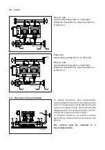
Intake side:
swap blanking flange (Item 1) to other end
96202500_00
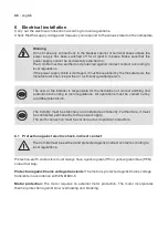
96202500_00
96202500_00
1
96202500_00
1
96202500_00
2
3
4
96202500_00
2
3
4
96202500_00
4
3
2
1
96202500_00
4
3
2
1
Montage Position
ComBo 2x HP-E 12-40-3/8
16 bar
CH-3110 Münsingen
Biral AG
Massstab
Zeichnungsnummer
1:10
Datum
Änd.Index
Visum
Ersetzt durch:
Ersatz für:
96202500
Änd.Index
Freigabe
geprüft
gezeichnet 03.04.2017
PDM_Nr
TD-0036171
00
22.05.2017
22.05.2017
ts
ts
ts
As supplied ComBo 2x / 3x / 4x HPE...
(non-return valve on pressure side)
96202500_00
96202500_00
96202500_00
1
96202500_00
1
96202500_00
2
3
4
96202500_00
2
3
4
96202500_00
4
3
2
1
96202500_00
4
3
2
1
Montage Position
ComBo 2x HP-E 12-40-3/8
16 bar
CH-3110 Münsingen
Biral AG
Massstab
Zeichnungsnummer
1:10
Datum
Änd.Index
Visum
Ersetzt durch:
Ersatz für:
96202500
Änd.Index
Freigabe
geprüft
gezeichnet 03.04.2017
PDM_Nr
TD-0036171
00
22.05.2017
22.05.2017
ts
ts
ts
96202504_00
Durcshflussrichtung auf Pumpe
ComBo 2x HP-E 12-40-3/8
BA
CH-3110 Münsingen
Biral AG
Massstab
Zeichnungsnummer
1:8
I
II
Datum
Änd.Index
Visum
Ersetzt durch:
Ersatz für:
96202504
Änd.Index
Freigabe
geprüft
gezeichnet 05.04.2017
PDM_Nr
TD-0033631
00
ts
5.3 Hydraulischer Anschluss
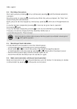
5.4 Arrangement of intake and pressure connections
The manifold comes with a screw cap fitted to one end. If this end is to be used, remove the screw
cap, apply sealing compound to the other end of the manifold, and fit the screw. Fit a blanking
flange with gasket on flanged manifolds.
Arrows on the pump base show the direction
of flow of water through the pump.
The pipes connected to the booster system
must be of adequate size


