


M
M
M
7
7
7
V
V
V
I
I
I
Z
Z
Z
4
4
4
0
0
0
0
0
0
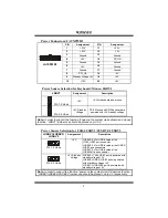
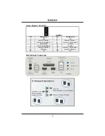
System Fan Header: JSFAN1
Pin
Assignment
1
Ground
2
+12V
1
JSFAN1
3
FAN RPM rate Sense
DDR DIMM Modules: DDR1, DDR2
DRAM Access Time: 2.5V Unbuffered/ Registered DDR 200 MHz (PC1600)/
DDR 266 MHz (PC2100)/ DDR 333 MHz (PC2700) Type required.
DRAM Type: 64MB/ 128MB/ 256MB/ 512MB/ 1GB DIMM Module (184 pin)
DIMM Socket
Location
DDR Module
Total Memory
Size (MB)
DDR 1
64MB/128MB/256MB/512MB/1GB *1
DDR 2
64MB/128MB/256MB/512MB/1GB *1
Max is
2GB
***Only for reference***
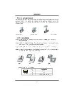
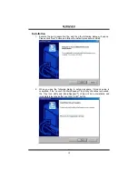
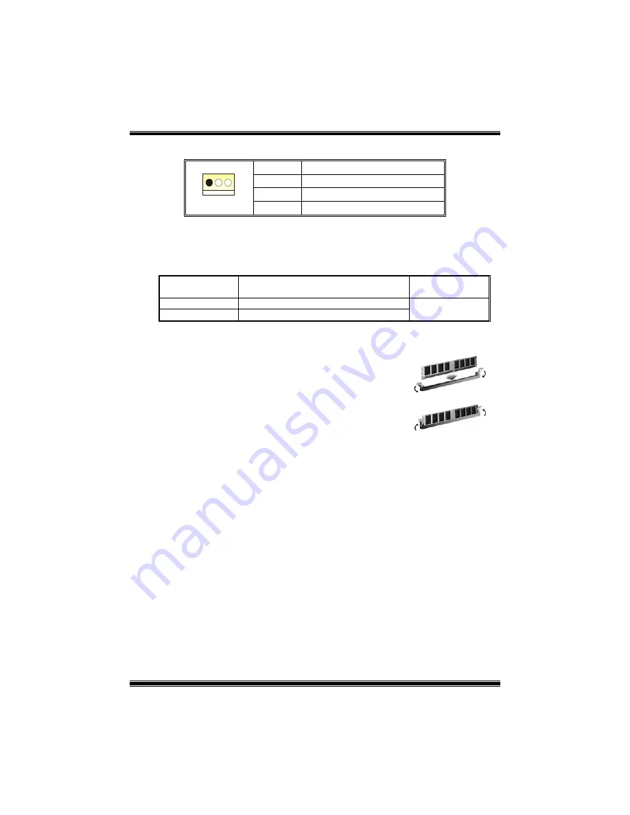
Installing DDR Module
1. Unlock a DIMM slot by pressing the retaining clips
outward. Align a DIMM on the slot such that the notch
on the DIMM matches the break on the slot.
2. Insert the DIMM vertically and firmly into the slot until
the retaining chip snap back in place and the DIMM is
properly seated.
Jumpers, Headers, Connectors & Slots
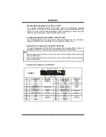
Floppy Disk Connector: FDD1
The motherboard provides a standard floppy disk connector that supports 360K,
720K, 1.2M, 1.44M and 2.88M floppy disk types. This connector supports the
provided floppy drive ribbon cables.
Hard Disk Connectors: IDE1/ IDE2
The motherboard has a 32-bit Enhanced PCI IDE Controller that provides PIO
Mode 0~5, Bus Master, and Ultra DMA 33/ 66/ 100/ 133 functionality. It has two
HDD connectors IDE1 (primary) and IDE2 (secondary).
The IDE connectors can connect a master and a slave drive, so you can connect
up to four hard disk drives. The first hard drive should always be connected to
IDE1.
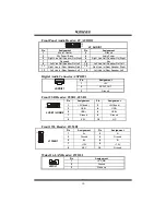
Peripheral Component Interconnect Slots: PCI 1-3
This motherboard is equipped with 3 standard PCI slots. PCI stands for Peripheral
Component Interconnect, and it is a bus standard for expansion cards. This PCI
slot is designated as 32 bits.
6


