EN - 10
6 Putting into operation
M-Drive
6.2 Establishing connections
6.3 M-Drive &
e
BOX
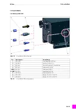
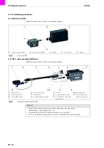
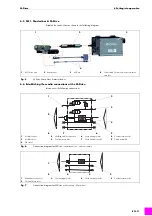
Establish the connections as shown in the following diagram:
6.4 MF1, cable assembly & M-Drive
Establish the connections as shown in the following diagram:
1
Port for control lead X46
2
Port for control lead X11
3
e
BOX
4
Control lead
5
M-Drive
Fig. 3
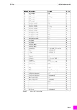
M-Drive &
e
BOX
1
4
2
5
3
1
MF1 drive unit
2
Motor control lead
3
VTS cable assembly
4
Motor control lead
5
Air-blast hose
6
Coolant supply hose (blue)
7
M-Drive
8
Coolant return hose (red)
9
Control lead for wire actual
value encoder
10
Wire inlet tube
11
Control lead for wire
actual value encoder
Fig. 4
Standard & masterfeeder M-Drive
11
4
5
1
2
7
10
3
9
6
8
NOTICE
• Ensure that the coolant supply and return hoses have been correctly installed.
Coolant supply = blue, coolant return = red
• We recommend using BTC-50 coolant; suitable for use at up to 50°C.
• To ensure the maximum cooling capacity, check the condition of the coolant regularly.
Summary of Contents for 881.3112
Page 106: ...ES 28 Notas M Drive Notas ...
Page 107: ...M Drive Notas ES 29 Notas ...


