background image

3

Installation, Operation and Maintenance Manual 

MAN 571_EAC Rev. 1

September 2020

General Warnings

Section 1: General Warnings

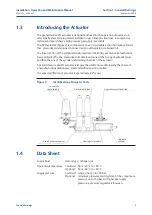
The GPO actuator (Figure 2) is composed of one or two double action hydraulic cylinders 
that, pressurized, determines the linear motion of the piston contained in it. 

The linear motion of the piston is transformed into rotation by a scotch yoke mechanism.

Gas sampled by the line, pressurizes oil contained in one of the two gas-hydraulic tanks 
and then the one of the cylinder determining the drive of the actuator.

A peculiar feature of GPO actuator is its great flexibility of use obtained by the choice of 
a manufacturing solution easy, solid and without parts in motion.

The expected lifetime of actuator is approximately 25 years .

Figure 2 

Identification of Actuator Parts

1.3 

Introducing the Actuator

The gas hydraulic GPO actuator is designed and used for the operation of quarter-turn 
valves (ball valves and plug valves) installed on gas transportation lines, in compressor 
stations and everywhere a high pressure gas supply is available.

Hydraulic manual override

Gas-hydraulic tanks

Flow-regulator valves

Pneumatic 

control group

Scotch yoke mechanism

Hydraulic 

cylinder

1.4 

Data Sheet

Supply fluid  

Natural gas / nitrogen /air

Operating temperature  Standard:  from –20 °C to +80 °C
 

Optional:  from –60 °C to +80 °C

Supply pressure 

Standard:  ranging from 7 to 100 bar.


 Optional:   minimum pressures starting from 3,5 bar, maximum 

pressure up to 160 bar. For higher gas supply 
pressure, a pressure regulator is foreseen.

Summary of Contents for GPO Series

Page 1: ...Actuator Copyright Biffi The information in this document is subject to change without notice Updated data sheets can be obtained from our website www biffi it or from your nearest Biffi Center Biffi...

Page 2: ...and Maintenance Manual MAN 571_EAC Rev 1 Revision Details Revision Details Rev Date Description Prepared Approved 1 September 2020 General update migration to new template 0 October 2017 Document rel...

Page 3: ...rocedure If Oil Leaks from the Tanks into the Pneumatic Valves 12 2 3 Storage 13 2 4 Actuator Assembly on the Valve 13 2 4 1 Types of Assembly 13 2 4 2 Assembly Procedure 18 2 5 Pneumatic Connections...

Page 4: ...enance 38 5 2 1 Lubrication of Mechanism 38 5 2 2 Replacing the Seals of the Cylinder 39 5 3 Dismantling and Demolition 40 Section 6 Troubleshooting 6 1 Failure or Breakdown Research 41 Section 7 Layo...

Page 5: ...y 2014 34 EU Directive and safety instructions for use in hazardous area TR TS 004 2011 Customs Union Technical Regulation For safety of low voltage equipment TR TS 010 2011 Customs Union Technical Re...

Page 6: ...in the documentation forwarded together with the product This warranty does not cover special products or components not warranted by subcontractors or materials that were used or installed improperly...

Page 7: ...olid and without parts in motion The expected lifetime of actuator is approximately 25 years Figure 2 Identification of Actuator Parts 1 3 Introducing the Actuator The gas hydraulic GPO actuator is de...

Page 8: ...e actuator is received already assembled with the valve its settings have already been made at the factory If the actuator is delivered separately from the valve it is necessary to check and if requir...

Page 9: ...5 Installation Operation and Maintenance Manual MAN 571_EAC Rev 1 September 2020 Installation Section 2 Installation Figure 3 Lifting Points...

Page 10: ...ation and Maintenance Manual MAN 571_EAC Rev 1 Installation Section 2 Installation Figure 4 Lifting Points 1 Point of support 2 Don t lay the actuator on tie rods 1 2 Lifting points obligatory 3 Balan...

Page 11: ...rrect functioning of GPO actuator If the actuator for reason of transport dimensions must be boxed in horizontal position it is mandatory to isolate the oil inside of the gas hydraulic tanks to avoid...

Page 12: ...tion Operation and Maintenance Manual MAN 571_EAC Rev 1 Installation Section 2 Installation Disassembly for shipping Figure 7 Unloose the nuts of the compression fittings R on pneumatic connections ni...

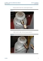
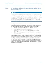
Page 13: ...ntenance Manual MAN 571_EAC Rev 1 September 2020 Installation Section 2 Installation Remove pneumatic tubes T from connection nipple S Figure 9 Figure 9 Plug the connection nipple S with proper cap pl...

Page 14: ...on plugs from compression fittings R and connections S Connect pneumatic tubes T to connections S NOTICE Check that the ferrule inside the conical seat of the fitting is aligned with the axis of the p...

Page 15: ...onnections S1 S2 by unloosing the nuts of the compression fittings R Figure 12 Plug the torque limiting switch with proper cap plugs on S connections Plug the pipe ends with suitable plugs for fitting...

Page 16: ...correct oil level can be verified by means of the oil dipsticks mounted on the top of each bottle To do this correctly we must equalize the oil level of the two bottles Bring the actuator to the middl...

Page 17: ...tion disc the valve coupling area Periodically operate the actuator Section 3 3 2 4 Actuator Assembly on the Valve 2 4 1 Types of Assembly For coupling to the valve the housing is provided with a flan...

Page 18: ...00 28 212 8 September 2020 Installation Operation and Maintenance Manual MAN 571_EAC Rev 1 Installation Section 2 Installation Dimensions in millimeters Actuator model d1 d2 d3 d4 N h1 h2 H max d5 W K...

Page 19: ...8 42 840 310 603 M36 16 12 32 400 220 50 242 8 Installation Operation and Maintenance Manual MAN 571_EAC Rev 1 September 2020 Installation Section 2 Installation Dimensions in millimeters Actuator mo...

Page 20: ...15 Drive sleeve N THREADED HOLES Flange sizing according to ISO Top view of the scotch yoke mechanism actuator shown in closed position Flow line Table 3 If required for the standard models size 0 3...

Page 21: ...the yoke can be machined according to the dimensions of valve stem Flow line N 4 holes flange N 8 holes flange Drive sleeve Snap ring Housing Insert bush Insert bush Adaptor flange Drive sleeve Standa...

Page 22: ...s of actuator valve coupling Operate the actuator so that it reaches the position matching valve position Section 3 3 Lubricate valve stem with oil or grease Properly clean and remove grease from coup...

Page 23: ...nd connections appropriate as for type material and dimensions Properly de burr the ends of rigid pipes Properly clean the interior of pipes sending through them plenty of the supply fluid used in the...

Page 24: ...pment until 19 April 2016 2014 35 EU from 20 April 2016 2004 108 EC Directive for the electromagnetic compatibility until19 April 2016 2014 30 EU from 20 April 2016 94 9 CE Directive and safety instru...

Page 25: ...that the values of pneumatic supply available in the system are compatible with those reported on the identification plate of the actuator Figure 1 Check that electrical values of supply to the contr...

Page 26: ...hamber of the cylinder this starts the linear motion of the piston and the consequent rotation motion of the scocth yoke to which the valve stem is coupled Oil discharged from the chamber of the cylin...

Page 27: ...n the actuator output torque exceeds the set value The torque limiting switch 772 stops the gas flow to the relevant gas hydraulic tank 4 and the enclosed gas is exhausted Note the operating diagram i...

Page 28: ...reducing the gas supply pressure at a preset value The torque limiting device consist of 2 valves one for each gas over oil tank which stop the gas flow coming from the pneumatic control valves of the...

Page 29: ...ow control valves see Figure 20 and Section 3 6 3 2 Residual Risks WARNING It is recommended to pipe exhaust gas The actuator has parts under pressure Use the due caution Use individual protections pr...

Page 30: ...ect operation of the actuator through the visual position indicator Release the lever to terminate the operation 3 3 2 Local Hydraulic Manual Operation WARNING Use the proper safety measures to protec...

Page 31: ...peration In case of remote control arrange the distributor to Automatic position Figure 22 and from the control room send the electric signal corresponding to the operation to carry out opening or clo...

Page 32: ...en 82 98 4 with respect to the nominal positions of complete opening and closing by means the mechanical stops screwed into the left side of the housing open valve and into the end flange of the pneum...

Page 33: ...ked with the special wrench c3 Turn counter clockwise to increase the angular stroke turn clockwise to decrease it When the adjustment is over tighten the plug t Figure 25 Mechanical Stop of the Cylin...

Page 34: ...tch box WARNING Refer only to technical documentation related to installed switch box model NOTICE Operate only the micro switch corresponding to the direction of operation being carried out as clearl...

Page 35: ...31 Installation Operation and Maintenance Manual MAN 571_EAC Rev 1 September 2020 Operation and Use Section 3 Operation and Use Figure 28 Micro switches Box Figure 29 Cam Adjustment...

Page 36: ...ntil reaching its proper positioning Put the roll pin back in its position NOTICE End of stroke micro switches should be operated before the stop of the stroke of the actuator due to mechanical stops...

Page 37: ...uate Allen wrench and follow these steps Figure 32 Remove the cap nut Loosen the locknut Screw with a screwdriver the setting screw to increase the operation time Unscrew with a screwdriver the settin...

Page 38: ...nal Tests and Inspections Section 4 Operational Tests and Inspections Section 4 Operational Tests and Inspections NOTICE To ensure the guaranteed SIL grade according to IEC 61508 the functionality of...

Page 39: ...ance needs NOTICE Periodicity and regularity of inspections is particularly influenced by specific environmental and working conditions They can be initially determined experimentally and then be impr...

Page 40: ...ould not be ABOVE MINIMUM in one tank and at the same time ABOVE MAXIMUM in the other one If in one tank level is BELOW MINIMUM and at the same time in the other tank it is ABOVE MAXIMUM or the other...

Page 41: ...YSPIN AWS22 Low temperature conditions until 46 C Manufacturer SHELL Name AEROSHELL FLUID 41 Viscosity at 54 C 2300 cST Viscosity at 40 C 491 cST Viscosity at 40 C 14 1 cST Viscosity at 100 C 5 3 cST...

Page 42: ...r In larger actuators the lubrication can be performed through the inspection holes of cover after removing the plugs The following grease is used by Biffi for standard working temperature and suggest...

Page 43: ...ghtness ring of the piston 9 and the guide ring 8 from their slots in the piston Properly clean the seat of the guide ring 8 and lubricate it with a lot of grease so that it keeps the ring in its plac...

Page 44: ...from the control unit and from the accumulator tank if present If actuator is still mounted onto the valve loosen the threaded connections between valve and actuator screws tie rods nuts Lift the act...

Page 45: ...Low supply pressure Restore Section 1 4 Wrong calibration of flow regulator valves Restore Section 3 6 Wear of the valve Replace Actuator too fast High supply pressure Restore Section 1 4 Wrong calib...

Page 46: ...der confirmation concerning all the supply and serial number of the actuator Section 1 2 for any specific spare part for a specific actuator model Please send every spare parts request to Biffi Italia...

Page 47: ...ess steel 4 1 Housing Carbon steel 5 1 Guide bar Alloy steel 6 1 Yoke Carbon steel 7 1 Cover gasket Fiber 8 1 Guide block Carbon steel 9 1 Bushing Steel Bronze PTFE 10 2 Sliding block Bronze 11 1 Vent...

Page 48: ...loy steel 7 1 Piston Nickel plated carbon steel 8 2 Guide sliding ring for piston PTFE graphite 9 1 Piston seal ring PTFE NBR rubber 10 4 Tie rod Alloy steel ASTM A320 gr L7 11 1 Stop setting screw Al...

Page 49: ...cription Material 1 1 Screw Alloy steel 2 1 Nut Carbon steel 3 1 Nut Carbon steel 4 4 Screw Alloy steel 5 2 Flange Carbon steel 6 2 Gasket Fiber 7 1 Stopper bush Alloy steel 8 1 Plug Alloy steel 9 1 A...

Page 50: ...al MAN 571_EAC Rev 1 Layouts Section 7 Layouts Figure 37 Hydraulic Manual Override Table 12 Parts List Item Qty Description Material 1 1 Handpump Carbon steel 2 1 Hand operated directional control val...

Page 51: ...ing retainer ring Carbon steel 7 1 Fork Carbon steel 8 2 Pin Stainless steel 9 4 Retainer ring Carbon steel 10 1 Rod Chromium plated alloy steel 11 1 Body Carbon steel 12 1 Lever Carbon steel 13 1 Spl...

Page 52: ...48 September 2020 Installation Operation and Maintenance Manual MAN 571_EAC Rev 1 Layouts Section 7 Layouts Figure 39 Hand Operated Directional Control Valve...

Page 53: ...15 1 Screw Stainlees steel 16 4 Spring washer Alloy steel 17 1 Back up ring PTFE 18 1 O ring NBR rubber 19 1 O ring NBR rubber 20 4 Screw Carbon steel 21 4 Spring washer Alloy steel 22 2 Screw Stainle...

Page 54: ...Nut Carbon steel 6 1 Nut Carbon steel 7 1 Retainer ring Spring steel 8 1 Flow control valve flange Carbon steel 9 1 O ring NBR rubber 10 1 O ring NBR rubber 11 1 Flow control valve setting screw Stai...

Page 55: ...ayouts Item Qty Description Material 1 1 Plug Carbon steel 2 1 Tank Carbon steel 3 1 Level stik Carbon steel 4 1 Plate Carbon steel 5 3 Spring washer Carbon steel 6 3 Screw Carbon steel 7 1 Plug Carbo...

Page 56: ...d every 10 years as of the date of first installation Openings will be closed again with the same mode as provided for by the first paragraph of Section 1 3 4 The transportation of tanks marked CE fro...

Page 57: ...intenance Operations Section 9 Date Report for Maintenance Operations Section 9 Date Report for Maintenance Operations Last maintenance operation date in factory on delivery exec by exec by exec by Ne...

Page 58: ...ublication are presented for information purposes only and while every effort has been made to ensure their accuracy they are not to be construed as warranties or guarantees express or implied regardi...

Reviews: