BFT PHEBE Installation And User Manual Download Page 4

USER’S MANUAL

ENGLISH

Thank you for buying this product, our company is sure that you will be more 
than satisfied with the product’s performance. The product is supplied with 
a “

Warnings

” leaflet and an “

Instruction booklet

”. These should both be 

read carefully as they provide important information about safety, installa-
tion, operation and maintenance. This product complies with the recognised 
technical  standards  and  safety  regulations. We  declare  that  this  product 
is in conformity with the following European Directives: 89/336/EEC and 
73/23/EEC (and subsequent amendments).

1) GENERAL OUTLINE

This controller has been designed to motorize counter-balanced overhead 
doors. The compactness and versatility of the installation allow the motor drive to 
be fitted to almost any model of overhead door where it can be installed both in 
the centre and at the side. It is particularly recommended for residential use.
The irreversible gearmotor keeps the door locked in the closing position 
without electric lock.
In the case where the mains power supply is off, release is activated from 
the inside by means of an appropriate knob. The release device if provided 
with microswitches, which stop the motor both on opening and on closing, 
and with a timed courtesy light.  

2) SAFETY

If correctly installed and used, this automation device satisfies the required 
safety level standards. However, it is advisable to observe some practical 
rules in order to avoid accidental problems.  
Before using the automation device, carefully read the operation instructions 
and keep them for future reference.
•  Keep children, persons and things outside the automation working area, 

particularly during operation. 

•  Keep radio control or other control devices out of children’s reach, in 

order to avoid any unintentional automation activation. 

•  Do not intentionally oppose the leaf movement. 
•  Do not attempt to open the gate by hand, if the actuator has not been 

released by means of the appropriate release knob.  

•  Do not modify the automation components. 
•  In case of malfunction, disconnect the power supply, activate the emer-

gency release to gain access to the actuator and request the assistance 
of a qualified technician (installer). 

•  Before proceeding to any external cleaning operation, disconnect the 

mains powers supply and at least one of the battery pole, if fitted. 

•  Keep the photocell optical components and luminous signal indication 

devices clean. Check that the safety devices (photocells) are not obscured 
by branches or shrubs.

•  For any direct assistance to the automation system, request the assistance 

of a qualified technician (installer). 

•  Have qualified personnel check the automation system once a year.
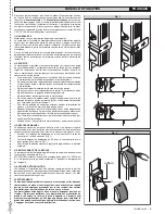
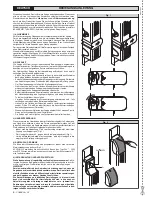
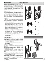
3) MANUAL RELEASE

The manual or emergency release is to be activated when the door must 
be opened manually, and any time the operator stops working or shows 
malfunctions. To carry out the emergency manoeuvre, proceed as follows:
•  Access the release knob by sliding its cover C until it stops (Fig.1).
•  Rotate the release knob by 90° anticlockwise (Fig.1).
•  To restore motor-driven operation, return the knob to its original posi-

tion. 

4) BULB REPLACEMENT

To replace the courtesy light bulb, remove its transparent cover (Fig.2).
WARNING: Only 24V  25W max E14 bulbs must be used.
Do not remove protection sheath “G” while replacing the bulb. 

5) MAINTENANCE AND DEMOLITION

The  maintenance  of  the  system  should  only  be  carried  out  by  qualified 
personnel regularly

.

 The materials making up the set and its packing must 

be disposed of according to the regulations in force.

WARNINGS

Correct controller operation is only ensured when the data contained 

in the present manual are observed. The company is not to be held 

responsible  for  any  damage  resulting  from  failure  to  observe 

the  installation  standards


and  the  instructions  contained  in  the 

present manual.

The descriptions and illustrations contained in the present manual are 

not binding. The Company reserves the right to make any alterations 

deemed appropriate for the technical, manufacturing and commercial 

improvement of the product, while leaving the essential product fea-

tures unchanged, at any time and without undertaking to update the 

present publication.

Fig. 1

Fig. 2

24V    25W

G

4 -


PHEBE Ver. 03

D811328_03

D811328_03

D811328_03

D811328_03

Summary of Contents for PHEBE

Page 1: ...EBE Via Lago di Vico 44 36015 Schio VI Tel naz 0445 696511 Tel int 39 0445 696533 Fax 0445 696522 Internet www bft it E mail sales bft it I GB F D E P MOTORIZZAZIONE PER PORTE BASCULANTI A CONTRAPPESO...

Page 2: ...2 PHEBE Ver 03 D811328_03 D811328_03 D811328_03 D811328_03...

Page 3: ...sblocco di emergenza per consentire l accesso e richiedere l intervento di un tecnico quali cato installatore Per ogni operazione di pulizia esterna togliere l alimentazione di rete e se presente alme...

Page 4: ...of malfunction disconnect the power supply activate the emer gency release to gain access to the actuator and request the assistance of a quali ed technician installer Before proceeding to any extern...

Page 5: ...intervention d un technicien quali installateur Pour toute op ration de nettoyage ext rieur couper l alimentation de ligne et si pr sent au moins un p le des batteries Nettoyer les optiques des cellul...

Page 6: ...t tigung der Notfallentsperrung den Zugang erm glichen und einen fachkundigen Techniker Installateur hinzuziehen Vor jeder Au enreinigung die Stromversorgung unterbrechen und falls vorhanden zumindest...

Page 7: ...la intervenci n de un t cnico cuali cado instalador Antes de realizar cualquier operaci n de limpieza externa cortar el suministro de corriente y si est presente el kit de bater as tamp n desconectar...

Page 8: ...loqueio de emerg ncia para consentir o acesso e solicitar a presen a de um t cnico quali cado Em toda opera o de limpeza externa desligar a alimenta o el ctrica Manter limpas a guia de rolamento as pa...

Page 9: ...comando alla portata dei bambini onde evitare azionamenti involontari dell automazione L utilizzatore deve evitare qualsiasi tentativo di intervento o riparazione dell automazione e rivolgersi solo a...

Page 10: ...me vigenti e comunque ai principi di buona tecnica I conduttori alimentati con tensioni diverse devono essere sicamente separati oppure devono essere adeguatamente isolati con isolamento supplementare...

Page 11: ...utenzioniperiodiche Controllareeventualmente il serraggio delle viti di ssaggio e l ingrassaggio dei bracci telescopici Veri care i dispositivi di sicurezza della porta e della motorizzazione Controll...

Page 12: ...vices out of children s reach in order to avoid unintentional automation activation Theusermustavoidanyattempttocarryoutworkorrepairontheautoma tion system and always request the assistance of quali e...

Page 13: ...nd split pin supplied 10 Insert the driving shafts T g 18 in the corresponding square housings of the driving arms make through holes in the shafts and bushes and fasten using through screws and nuts...

Page 14: ...uator does not require periodical maintenance operations If neces sary check that the screws are properly tightened and that the telescopic arms are adequately greased Check the safety devices of the...

Page 15: ...autoris es par la Soci t Informer l utilisateur de l installation sur les syst mes de commande appliqu s et sur l ex cution de l ouverture manuelle en cas d urgence Ne pas permettre des personnes et...

Page 16: ...le trou de la xation A et le centre de l arbre de transmis sion 7 Couper le guide bras et le bras du moteur en respectant les mesures indiqu es dans la g 15 la cote D est la distance pr c demment obte...

Page 17: ...tredetypediff rent manuelle avec radio commande contr le des acc s avec carte magn tique etc selon les besoins et les caract ristiques de l installation Pour les diff rents syst mes de commande voir...

Page 18: ...ist es nicht gestattet im Aktionsbereich der Anlage zu verweilen Keine Fernbedienungen oder andere Steuerungsvorrichtungen in Reich weite von Kindern liegenlassen Sie k nnten die Anlage versehentlich...

Page 19: ...tung der Werte aus Fig 15 abtrennen der Wert D stellt den gerade ermittelten Abstand dar 8 WenndieMa eausFig 15wegenunzureichenderL ngenichteingehalten werdenk nnen untersuchen obbeigeschlossenemTorde...

Page 20: ...euerung manuell mit Fernbedienung Zugangskontrolle mit Magnetkarte etc die auf Bedarf und Anlagenmerkmale zugeschnitten sind Informationen zu den diversen Steuerungssystemen entnehmen Sie bitte der je...

Page 21: ...la ejecuci n de la apertura manual en caso de emergencia No permitir que personas o ni os estacionen en el campo de acci n del automatismo No dejar radiomandos u otros dispositivos de mando al alcance...

Page 22: ...encontrarse una posici n m s id nea para la uni n A o utilizar brazos m s largos 9 Fijar el brazo telesc pico a la uni n A g 17 con el perno y la clavija asignados 10 Encajar los rboles de transmisi n...

Page 23: ...ionamiento y el uso del mismo 14 MANTENIMIENTO Antes de realizar cualquier operaci n de mantenimiento es preciso cortar el suministro de corriente al automatismo El servomotor no requiere un mantenimi...

Page 24: ...ccionamentos involunt rios da automatiza o O utilizador deve evitar qualquer tentativa de interven o ou repara o da automatiza o e valer se unicamente de pessoal quali cado Tudo aquilo que n o express...

Page 25: ...re completamente eixos e casquilhos e xe com parafusos passantes e porcas 6 PREDISPOSI O DA INSTALA O EL CTRICA RECOMENDA ES Nas opera es de cablagem e instala o fa a refer ncia s normas legais e t cn...

Page 26: ...i dicas Controle eventu almente o aperto dos parafusos de xa o e a lubri ca o dos bra os telesc picos Controle os dispositivos de seguran a da porta e da motoriza o Controle periodicamente a for a de...

Page 27: ...2 Fig 3 B F C S 615 870 H 1 2 H 1 3 H 1 3 H 1 3 H 1 2 H 110mm 70 80 mm 70 80 mm 150mm PHEBE C A A B B B B A A 870 615 113mm 129 mm 148 mm 114mm 249 mm 330 mm 579 mm 100 D811328_03 D811328_03 PHEBE Ver...

Page 28: ...Fig 9 Fig 10 Fig 11 Fig 12 Fig 7 Fig 8 T T B S A S C B C B 2 5mm 1 2 1 2 S 15 28 PHEBE Ver 03 D811328_03 D811328_03 D811328_03 D811328_03...

Page 29: ...Fig 15 Fig 16 Fig 17 Fig 13 Fig 14 A A S 7 0 8 0 m m C S A A S S S 1 2 1 2 C A A A A Y 60 X 35 D 25mm 25mm 30mm 70mm D D811328_03 D811328_03 PHEBE Ver 03 29 D811328_03 D811328_03...

Page 30: ...10m max A 2 7x1mm2 L N GND 3x1 5mm 2 PHEBE 2x2 5 mm2 B 2 7x1mm 2 6x1mm 2 4x2 5 mm 2 2x1 5mm 2 L N GND 3x1 5mm 2 HYDRA PHEBE SQ 2x2 5 mm2 C 2 7x1mm2 3x1mm2 PHEBE SQ PHEBE SQ HYDRA 4x2 5 mm 2 2x1 5mm 2...

Page 31: ...C Close 2 FC Open 2 1 2 A DIN 2 5 PHEBE HYDRA 1 2 3 4 5 6 7 8 9 10 11 12 13 14 15 16 PHEBE SQ GND OK 8888 0 25V 3 4 5 6 7 8 9 10 11 12 13 14 15 16 17 18 19 20 21 22 23 24 25 26 27 28 D811328_03 D81132...

Page 32: ......

Reviews: