


INSTALLATION MANUAL
ENGLISH
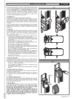
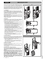
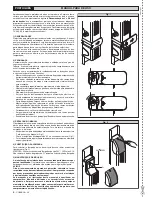
sions in fig.2).
NOTE: It is advisable to fit the actuator cover only after completing the
installation, using the four screws (B) (Fig.2); this makes it possible to
access the control panel and to adjust the limit switches.
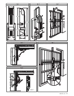
• The fixing position of the actuator changes according to the type of over-
head door. In the case of counter-balanced overhead doors with vertical
guide (fig. 3) the axis of the actuator driving shaft, must be about 70-80
mm lower than the fulcrum “F” of the already existing panel levers.
• For overhead doors with vertical and horizontal guides, the axis of the
actuator must be about 100-110 mm lower than half the total height of
the door (fig. 4).
• In the case of articulated-panel overhead doors, use PHEBE-C. The
actuator axis must be positioned about 150mm lower than the articulated
hinge “C” (fig.5).
• Remove the fixing base surplus “B” exceeding the overhead door panel
(fig. 3).
• Make some fixing holes in the base and secure it to the panel using
fasteners suited to the type of overhead door (screws, rivets etc.). The
fixing points must be made in reinforced points of the panel and, if pos-
sible, under the motor.
5.3) Driving shaft assembly
• Fasten the two side shaft supports “S” to the panel (fig. 6).These should
be fastened securely to the frame of the overhead door and should be
perfectly aligned with the actuator shaft hole.
• Position the shaft adaptor bushes “B” in both the supports “S” and insert
the square driving pipes “T” until they enter the housing of the actuator
shaft “A” (fig. 7).
• Cut the shaft surplus in keeping with the measurements given in fig. 8
where “B” is the and “C” is the counter-weight case.
5.4) Balancing of overhead door
• Carry out the manual opening of the overhead door. If when the actuator
is installed, the door is no longer balanced (fig. 9), increase the counter-
weighting as follows:
• Remove the guards of the counter-weight cases, release the counter-
weights and add weights “P” (iron plates) until the balancing of the door
is achieved.
N.B. If the actuator is installed in a central position, increase the counter-
weights in an equal amount.
• If the (single) actuator is installed at the side, add more weight to the
actuator side.The lateral installation is possible provided that the structure
of the overhead door panel is strong enough to transmit the movement
from one side only.
• If the counter-weights are made of iron, fasten the weights “P” by weld-
ing (fig. 9). If the counter-weights are made of other materials, fasten the
weights “P” in the most appropriate way.
5.5) Telescopic arm assembly
WARNING: Before rotating the actuator shaft, check that the cams
controlling the microswitches - limit switches rotate freely (loose).
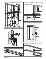
1) If the overhead door measurement shown in fig. 10, is 15 mm or more,
fit the straight telescopic arms (fig. 11).
2) If the overhead door measurement (fig. 10) is less than 15 mm, fit the
curved telescopic arms (fig. 12).
3) Position the upper fastener “A” (fig. 13) of each arm on both sides of the
overhead door.
4) The dimensions given in fig. 13 are merely indicative. They may vary
according to the overall dimensions of the door.
5) Weld the arm fasteners “A” Some overhead door models may already
have the fasteners “A” attached. In this case, check if they can be used
for the type of telescopic arms selected.
6) Open the overhead door completely and measure the distance D
(fig. 14) between the fastener hole “A” and the centre of the driving
shaft.
7) Cut the arm guide and the driving arm in keeping with the measurements
indicated in fig. 15 (value “D” is the distance previously obtained).
8) If the values given in fig. 15 cannot be observed because the telescopic
arm length is insufficient, check when the door is closed whether the
telescopic arm stays inserted for at least 70-80 mm (fig. 16). If this is not
the case, find a position more suitable for the fastener “A” or use longer
arms.
9) Secure the telescopic arm onto the fastener “A” (fig. 17) using the pin
and split pin supplied.
10)Insert the driving shafts “T” (fig. 18) in the corresponding square housings
of the driving arms, make through holes in the shafts and bushes and
fasten using through screws and nuts.
6) ELECTRICAL PLANT SET-UP
WARNINGS -
For wiring
and installation operations, refer to the current
standards and good technical principles.
Wires powered at different voltages must be physically separated, or suitably
insulated with at least 1 mm extra insulation. The wires must be clamped by
an extra fastener near the terminals, for example by bands.
6.1) Main components for one automation
(fig. 19)
:
I
Type approved omnipolar switch with 3,5 mm min. contact opening
provided with overload and short-circuit protection, used to break the
automation connection from the mains. If not present, provide the
automation with a type approved differential switch with adequate
capacity and a 0.03 A threshold.
M-Q-R)
Actuator with control unit with built-in receiver
CTBA)
Telescopic arms and transmission pipes
Fr)
Photocell (receiver)
Ft)
Photocell (transmistter)
T)
1-2-4 channel transmitter
CC)
Sensitive edge check
CS)
Sensitive edge
D)
Connector block
P)
Internal control push button strip
Set the electrical plant (fig. 19) according to the current standards for elec-
trical plants CEI 64-8, IEC364, Harmonization HD384 and other national
regulations. Keep the power supply connections definitely separated from
the auxiliary connections (photocells, sensitive edges, control devices,
etc.).
WARNING! For connection to the mains, use a multipolar cable with
a minimum of 3x1.5mm
2
cross section and complying with the previ-
ously mentioned regulations. For example, if the cable is out side (in
the open), it has to be at least equal to H07RN-F, but if it is on the inside
(or outside but placed in a plastic cable cannel) it has to be or at least
egual to H05VV-F with section 3x1.5mm
2
.
6.2) Connection arrangement
Fig. 20a-20b-20c-20d
show some examples of connections for the different arrangements.
Fig. 20a
One PHEBE or PHEBEKIT with pre-assembled control unit
Fig. 20b
One PHEBE-SQ with wall-mounted control unit
Fig. 20c
Two PHEBE-SQ with wall-mounted control unit mod. HYDRA
Fig. 20d
One PHEBE with pre-assembled control unit mod. HYDRA and
one PHEBE-SQ without control unit.
6.3) Cable passage
Fig. 21 shows the passage of the actuator cables. The casing features thin
walls to be cut using a pair of scissors.
If the overhead door is not provided with a central element where to pass
the connection cables (fig. 21), apply appropriate raceways.
The part of the cables between the wall and mobile door should form a
loop “A” (fig. 22) long enough to allow the movement of the door without
tensioning.
7) LIMIT SWITCH ADJUSTMENT
Remove the upper casing of the gearmotor, the limiting microswitches with
the corresponding cams are located on the left of the controller.
The upper microswitch controls stopping in the closing position “1”.
The lower microswitch controls stopping in the opening position “2”.
The two cams which control the microswitches are fitted to the output
shaft.
The cam should detect the microswitch command always on the side op-
posite to the fixing screw head of the cam.
The cams should be adjusted as follows:
Operate the manual release using the appropriate lever (fig. 26).
Close the door completely (fig. 23).
Turn the closing cam until the triggering of the upper microswitch “1” can be
heard and lock the cam in position by tightening the cam screw.
Open the door completely (fig. 24).
Turn the opening cam until the triggering of the lower microswitch “2” can be
heard and lock the cam in position by tightening the cam screw.
CAUTION: If the cams at the end of the manoeuvre do not intercept the
limiting microswitch, the motor will continue to run until the time set
on the control unit (TW) has elapsed.
Supply the system with power and check that the closing and opening posi-
tions are correct. If necessary adjust the cam position as required.
Make sure the cams are properly fastened and re-fit the upper casing of
the actuator.
D811328_03
D811328_03
PHEBE Ver. 03 -
13
D811328_03
D811328_03
Summary of Contents for PHEBE
Page 2: ...2 PHEBE Ver 03 D811328_03 D811328_03 D811328_03 D811328_03...
Page 32: ......