background image

ENGLISH

D

C

C1

1

45°

3

2

4

5

V1

V1

4

10

*

*

E

2

4

+ 45 °

- 45 °

- 45 °

+ 45 °

90 °

0 °

1

45°

 OK

45°

3

6

5

*


Not supplied

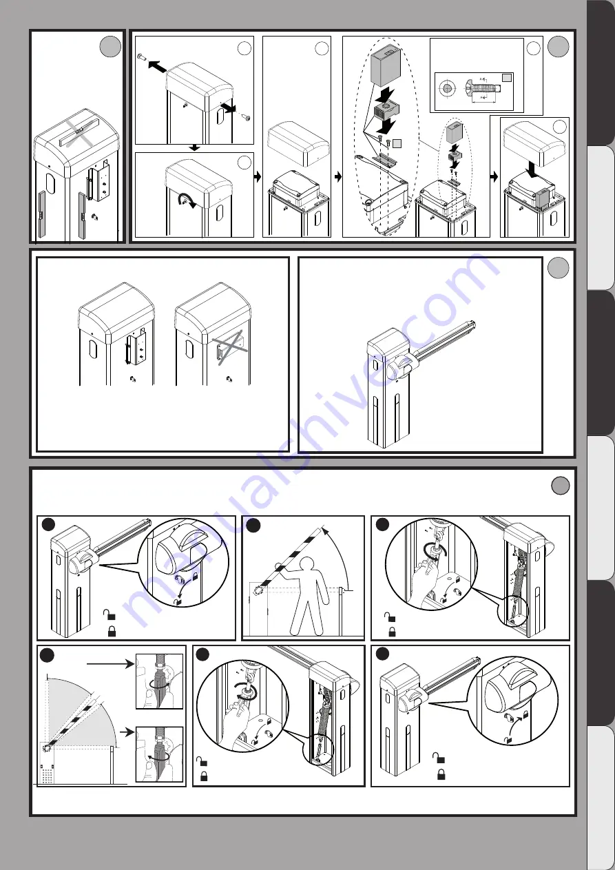
 Assembly of boom


Make sure the spring is not under tension.


See manuals for boom assembly

  Boom balancing

MANUAL -

AUTOMATIC 

MANUAL 

AUTOMATIC 

MANUAL  

AUTOMATIC 

MANUAL 

AUTOMATIC

GIOTTO BT A 30-60 S U / GIOTTO BT A 30-60 U   -

 17

D812433 00100_06

Summary of Contents for GIOTTO BT A 30 U

Page 1: ... ELECTROMECHANICAL CONTROL DEVICE FOR VEHICULAR BARRIERS A INSTALLATION AND USER S MANUAL GIO GIO T T T T O B O B T A 30 60S U T A 30 60S U GIO GIO T T T T O B O B T A 30 60 U T A 30 60 U Caution Read Warnings inside carefully ...

Page 2: ...movementsiftherearemechanical faults or loss of balance When using roller shutter openers keep an eye on the roller shutter while it is moving and keep peopleawayuntilithasclosedcompletely Exercise care when activating the release if such a device is fitted as an open shutter could drop quickly in the event of wear or breakage The breakage or wear of any mechanical parts of the door operated part ...

Page 3: ...USER S MANUAL MANUAL OPERATION Fig Y 8 GIOTTO BT A 30 60 S U GIOTTO BT A 30 60 U D812433 00100_06 ...

Page 4: ... least 1 5 m and in a place where they cannot be reached by the public Apply at least one warning light flashing light in a visible position and also attach a Warning sign to the structure Attach a label near the operating device in a permanent fashion with informa tion on how to operate the automated system s manual release Make sure that during operation mechanical risks are avoided or relevant ...

Page 5: ...5 mm 2 3 8 m m 70 mm 340 mm 2 2 0 m m 3m GIOTTO BT A 30S U GIOTTO BT A 30 U 6m GIOTTO BT A 60S U GIOTTO BT A 60 U I 2x0 75mm 2 3x0 75mm 2 B 45 90 5x0 75 mm 2 QR RMM S AL 3x0 75 M F Ft CF T Fr A CS GIOTTO BT A 30 60 S U GIOTTO BT A 30 60 U 15 D812433 00100_06 ...

Page 6: ... V 1 1 2 3 5 4 B1 V 12 35 B2 2 3 With foundation plate embedded in ground With anchor bolts Not supplied Not supplied 16 GIOTTO BT A 30 60 S U GIOTTO BT A 30 60 U D812433 00100_06 ...

Page 7: ... 45 OK 0 45 3 6 5 Not supplied Assembly of boom Make sure the spring is not under tension See manuals for boom assembly Boom balancing MANUAL AUTOMATIC MANUAL AUTOMATIC MANUAL AUTOMATIC MANUAL AUTOMATIC GIOTTO BT A 30 60 S U GIOTTO BT A 30 60 U 17 D812433 00100_06 ...

Page 8: ...m 5 m B MIN L 4 4 m 2 4 m 2 5 m 2 6 m 2 9 m 2 9 m 3 1 m 3 2 m 3 3 m 3 5 m 3 7 m 2 7 m 2 7 m 2 8 m 3 2 m 3 3 m 3 4 m 3 6 m 3 7 m 3 9 m MAX L 5 m 3 3 m 3 3 m 3 5 m 3 9 m 4 m 4 2 m 4 3 m 4 4 m 4 7 m 5 m 3 5 m 3 6 m 3 7 m 4 2 m 4 3 m 4 5 m 4 7 m 4 9 m 5 m A MIN L 2 4 m 2 5 m 2 5 m 2 9 m 2 9 m 2 7 m 2 7 m 2 8 m MAX L 2 7 m 2 7 m 2 8 m 3 m 3 m 2 9 m 2 9 m 3 m B MIN L 1 9 m 2 m 2 m 2 3 m 2 3 m 2 5 m 2 5 ...

Page 9: ...OTTO BT A U 120V 2 AT GIOTTO BT A S U 230V 4 AT GIOTTO BT A S U 120V F1 10 26 41 43 50 51 52 60 61 62 21 27 70 10 26 41 43 50 51 52 60 61 62 21 27 70 1 2 Terminal board wiring Optional board connector Display plus programming keys Power supply Motor Safety devices Commands Accessories power supply Limit switch assembly connection Palmtop programmer connector Encoder connector ITALIANO ENGLISH FRAN...

Page 10: ...2 AUX 0 6 24V 20 21 AUX0 24V MAX 1A 20 21 24V 26 27 26 27 AUX 3 0 AUX 3 2 AUX 3 3 AUX 3 4 AUX 3 5 AUX 3 6 AUX 3 7 AUX 3 8 AUX 3 9 AUX 3 10 AUX 3 12 AUX 3 12 AUX 3 12 AUX 3 1 24 V SCA 26 27 26 27 50 51 Connection To Car park Management System Connection of 1 pair of non tested photocells 20 GIOTTO BT A 30 60 S U GIOTTO BT A 30 60 U D812433 00100_06 ...

Page 11: ...ed button e hidden button re otes x1 0 10 150 1520 ok Exit Menù Confirm Switch on display Scroll up Scroll down language type 60 30 KEY PRESET DEFAULT ar sr ac sc ind PARAMETERS Automatic closing time s 10 10 10 5 5 5 LOGIC Automatic Closing Time 1 1 0 1 0 0 Step by step movement 1 1 0 1 0 0 Pre alarm 0 0 0 1 1 0 Deadman 0 0 0 0 0 1 Block pulses during opening 1 0 0 1 1 0 Password entry Request wi...

Page 12: ... acceler accel beschleunigung PRG ok OK P1 P2 70 PRG ok OK P1 P2 P2 3 x 2 x 2 OK default default default default default default freno brake frein bremse PRG ok OK P1 2 default cal ch clos calib cal ferm sch kal cal cie 1 1 Edit the following values until you are happy with boom movement PRELIMINARY ADJUSTMENTS ITALIANO ENGLISH FRANÇAIS DEUTSCH ESPAÑOL PORTUGUÊS ITALIANO ENGLISH FRANÇAIS DEUTSCH E...

Page 13: ...the spring is not under tension and the boom is not fitted Remove the spring assembly Ret the right hand spring assembly Open in other direction 1 Inversion Open in other direction 0 Inversion ASSEMBLY OF RIGHT BOOM 28 GIOTTO BT A 30 60 S U GIOTTO BT A 30 60 U D812433 00100_06 ...

Page 14: ...flashing light on the barrier using the screw V1 See the photocell s manuals and post mount s manuals for instructions on installing the photocell and photocell with post mount PLEASE NOTE Remove cover A B or C to install the photocell or post mount PLEASE NOTE Fasten the photocell on the barrier using the screw V2 Installing the flashing light Installing the photocells Installing the photocell wi...

Page 15: ...2 70 71 72 73 74 75 S1 S2 S3 OK F3 1 25A T 10 11 20 21 26 27 41 42 43 50 51 52 60 61 62 70 71 72 73 74 75 S1 S2 S3 OK 8888 L M S1 S2 S3 OK S1 S2 S3 OK 70 71 COM STOP S1 S2 S3 OK S1 S2 S3 OK 8888 rst8 8888 1 2 3 4 6 5 3s MASTER SLAVE CC1 BAR CC2 BAR ON OFF EXPANSION BOARD Universal palmtop programmer address 0 serial mode 3 address 0 serial mode 2 TO CONNECT SEVERAL PHOTOCELLS REFER TO FIG P 30 GIO...

Page 16: ...5 S 6 S 70 73 72 70 1 S 2 S 4 S 5 S 3 S 70 73 6 S 70 72 8 2Kohm 5 SAFETY EDGE SAFETY EDGE 1 SAFE1 6 3 2 5 4 SAFE 2 1 2 1 2 3 4 5 51 TX1 RX1 Bar 1 1 2 3 4 5 6 1 2 1 2 3 4 5 52 50 TX1 RX1 1 2 1 2 3 4 5 TX1 RX1 1 2 1 2 3 4 5 TX2 RX2 1 2 1 2 3 4 5 TX1 RX1 1 2 1 2 3 4 5 TX2 RX2 1 2 1 2 3 4 5 TX3 RX3 1 2 1 2 3 4 5 TX1 RX1 1 2 1 2 3 4 5 TX2 RX2 1 2 1 2 3 4 5 TX3 RX3 1 2 1 2 3 4 5 TX4 RX4 Bar 1 1 2 3 4 5 ...

Page 17: ...gic settings ER02 Safety edge test failed Check safety edge connection and or logic settings ER03 Opening photocell test failed Checkphotocellconnectionand orparameter logicsetting ER04 Closing photocell test failed Checkphotocellconnectionand orparameter logicsetting ER05 Safety edge test on slave motor failed opposite leaves connection Check safety edge connection and or parameter logic settings...

Page 18: ...ated in Fig A WARNING before opening the door the spring must be unloaded vertical boom The door of the box must be facing towards the inside oftheproperty Whenyoustandinthemiddleofthepassageway facing outwards if the box is on your left the barrier is left hand fitted if the box is on your right the barrier is right hand fitted The actuator is always supplied for left hand side fitting 6 Right ha...

Page 19: ...ferences 42 RIFC Reference closing RIFC N C 43 RIFO Reference opening RIFO N C Accessories power supply 50 24V Accessories power supply output 51 24V 52 24 Vsafe Tested safety device power supply output photocell transmitter and safety edge transmitter Output active only during operating cycle Commands 60 Common IC 1 and IC 2 inputs common 61 IC 1 Configurable command input 1 N O Default OPEN STAR...

Page 20: ...beam is broken photocell operation is disabled during opening During closing movement is reversed immediately SAFE logic 6 Input configured as Bar safety edge non tested fig N ref 3 Enables connection of devices not equipped with supplementary test contacts The command reverses movement for 2 sec If not used leave jumper inserted SAFE logic 7 Input configured as Bar tested safety edge fig N ref 4 ...

Page 21: ...ontactisthenopenedbytheStopcommandorbytheclosinglimitswitch open calib Specialpar 1 0 100 75 Opening value calibration Opening value calibration Set the reference value from 0 0 to 100 0 for the required opening position see Paragraph Limit Switch Setting clos calib Specialpar 6 0 100 25 Closing value calibration Closing value calibration Set the reference value from 0 0 to 100 0 for the required ...

Page 22: ... devices are not enabled IBL OPEN Block pulses during opening 1 0 Pulse from inputs configured as Start E Start I has effect during opening 1 Pulse from inputs configured as Start E Start I has no effect during opening IBL TCA Block pulses during TCA 0 0 Pulse from inputs configured as Start E Start I has effect during TCA pause 1 Pulse from inputs configured as Start E Start I has no effect durin...

Page 23: ...he board s parameters can be edited via the U link network 1 A You are prompted to enter the password to access the programming menus The default password is 1234 No change in behaviour of functions B C D E from 0 logic setting 2 A You are prompted to enter the password to access the programming menus The default password is 1234 B Wireless memorizing of transmitters is disabled C Wirelessautomati...

Page 24: ...command 6 Input configured as Timer Pedestrian command 7 Input configured as Phot photocell safety 8 Input configured as Phot op safety photocell active during opening only 9 Input configured as Phot cl safety photocell active during closing only 10 Input configured as Bar safety safety edge EXPO1 Configuration of EXPO2 output on input output expansion board 4 5 11 0 Output configured as 2nd Radio...

Page 25: ...O2 in de uitbreidingskaart ingangen uitgangen 6 7 11 6 Uitgang geconfigureerd als Knipperlicht 7 Uitgang geconfigureerd als Klikslot 8 Uitgang geconfigureerd als Magneetslot 9 Uitgang geconfigureerd als Onderhoud 10 Uitgang geconfigureerd als Zwaailicht en Onderhoud 11 Uitgang geconfigureerd als Beheer stoplicht met TLB kaart 12 uitgang geconfigureerd als status barrière TRAFFIC LIGHT PREFLASHING ...

Reviews:

Related manuals for GIOTTO BT A 30 U