


TEMPLATE
N
(2x)
M
C*
High edge of door bevel
Borde alto del bisel de la abertura
Bordure supérieure du biseau de la porte
2
Tools Needed
Herramientas necesarias
Outils nécessaires
7K Lock Installation Instruction
Instrucción de instalación de cerradura 7KC
Instructions d'installation de la serrure 7KC
Phillips Screwdriver
Destornillador Phillips
Tournevis Phillips
Flathead Screwdriver
Destornillador de cabeza plana
Tournevis à tête plate
Tape Rule
Flexómetro de Cinta
Mesure
A
B
C*
Control Key
Tecla de control
Clé de contrôle
Core 6-Pin or 7-Pin (Optional)
Núcleo de 6 o 7 clavijas (opcional)
Noyau à 6 ou 7 broches (en option)
Boring Jig
Plantilla de perforación
Gabarit d’alésage
Throw Member - For 6-Pin and 7-Pin Cores
Miembro de alzada: para núcleos de 6 o 7 clavijas
Pièce de projection — Pour noyaux à 6 et 7 broches
G
H
J
Chassis Assembly
Conjunto del chasis
Ensemble du barillet
Rose Liner
Revestimiento de rosa
Plaque de rosette
Through-Bolt Screws
Tornillos pasantes
Vis à boulon traversant
K
(2x)
L
M
Lever Handle
Palanca
Bec-de-cane
Latch Assembly
Conjunto del pestillo
Ensemble du loquet
Screw #8-32
Tornillo n.º 8-32
Vis nº 8-32
Standard Strike Plate
Placa de golpe de serie
Gâche standard
Standard Strike Box
Caja de golpe de serie
Boîtier métallique standard
N
(4x)
O
P
D
E
F
(2x)
Threaded Rose Liner
Revestimiento de rosa roscado
Plaque de rosette filetée
Lever Handle #15 Style
Palanca estilo n.º 15
Bec-de-cane de style no 15
Rose
Rosa
Rosette
Hole Saw
Sierra perforadora
Scie-cloche
Drill
Taladro
Perceuse
F
(2x)
F
(2x)
H
L
A
B
D
E
C*
G
N
(4x)
O
P
M
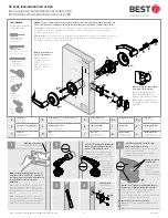
Note:
The suggested height from the floor to
centerline of the lock is 40 5/16" (102.4cm). If
steel frames are used, the latch centerline must
be in-line with the center of the strike
preparation.
Nota:
La altura sugerida desde el piso hasta la línea
central de la cerradura es 102.4 cm (40 5/16"). Si se
utilizan marcos de acero, la línea central del pestillo
debe estar alineada con el centro de preparación del
pasador.
Note :
La hauteur suggérée du sol au centre de la
serrure est de 102,4 cm (40 5/16 po). Si des cadres en
acier sont utilisés, la ligne centrale du loquet doit être
alignée avec le centre de la préparation de la gâche.
1
3
4
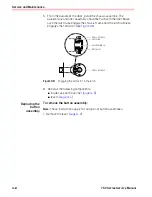
Install the boring jig (C*) with the edge
parallel to the edge of the door.
Instale la plantilla de perforación (C*) con el borde
paralelo al borde de la puerta.
Installez le gabarit d’alésage (C*) avec le bord
parallèle au bord de la porte.
Engage the jig with
the latch tabs.
Enganche la plantilla
con las pestañas del
pestillo.
Engagez le gabarit avec
les languettes du loquet.
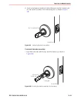
Drill two 5/16”(8mm) holes halfway into the door.
Turn the jig over and repeat from the other side.
Taladre dos orificios de 8 mm (5/16”) en la mitad de la
puerta. Gire la plantilla y repita en el otro lado.
Percez 2 trous de 8 mm (5/16 po) à mi-chemin dans la porte.
Retournez le gabarit et répétez de l’autre côté.
Note
: Replace jig after ten door preparations.
Nota:
Reemplace la plantilla después de diez preparaciones
de puertas.
Note :
Remplacez le gabarit après 10 préparations de porte.
Door edge
borde de la puerta bord de la porte
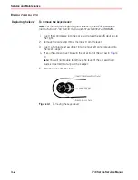
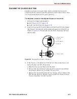
Drill a 2 1/8” (54mm) hole halfway into
the door. Repeat from the other side.
Drill a 1“ (25mm) hole for latch.
Taladre un orificio de 54 mm (2 1/8”) en la
mitad de la puerta. Repita en el otro lado.
Taladre un orificio de 25 mm (1“) para
el pestillo.
Percez un trou de 54
mm (2 1/8 po) à
mi-chemin dans la
porte. Répétez de
l’autre côté. Percez
un trou de 25 mm
(1 po) pour le
loquet.
*Note
: Boring jig part number KD303
not included, order separately.
*Nota:
La plantilla de perforación,
número de pieza KD303, no está
incluida, y debe pedirse por separado.
*Note :
Gabarit d’alésage numéro de
pièce KD303 non inclus, à commander
séparément.
Note
: For unprepared doors
reference 7KC templates.
Nota:
Para puertas no
preparadas, consulte las
plantillas 7KC.
Note :
Pour les portes non
préparées, consultez les
modèles 7KC.
Caution
: If you use hollow metal doors, determine whether the doors are reinforced enough to support the lock.
If door reinforcement is not adequate, consult the door manufacturer for information on proper reinforcement.
Precaución:
Si utiliza puertas metálicas huecas, determine si están lo suficientemente reforzadas como para soportar
la cerradura. Si el refuerzo de la puerta no es el adecuado, consulte con el fabricante de la puerta para obtener
información sobre el refuerzo correcto.
Mise en garde :
S
i vous utilisez des portes métalliques creuses, déterminez si les portes sont suffisamment renforcées
pour supporter la serrure. Si le renforcement de la porte n’est pas adéquat, consultez le fabricant de la porte pour
obtenir des informations sur le renforcement approprié.
Backset
Distancia de entr
ada
Écartement
Inside of door
dentro de la puerta
dentro de la puerta
5
L
1"
25mm
2 1/8"
54mm
1" (25.4mm) Chisel
1" (25.4mm) Cincel
1" (25.4mm) Ciseau
5/16"
8mm
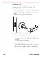
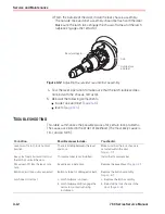
Install the latch.
Instale el pestillo.
Installez le loquet.
J
K
(2x)
T80622_D
1/2
BEST is a trademark of dormakaba USA Inc.
©
2021 All rights reserved.
Summary of Contents for 7KC Series
Page 1: ...7KC GRADE 2 CYLINDRICAL LOCKS 7KC SERIES S E R V I C E M A N U A L...
Page 6: ...Figures vi 7KC Series Service Manual...
Page 10: ...Getting Started 1 4 7KC Series Service Manual...
Page 22: ...Functions and Parts Lists 2 12 7KC Series Service Manual...
Page 36: ...Installation Instructions A 2 7KC Series Service Manual...
Page 41: ...T80621_C BEST is a trademark of dormakaba USA Inc 2021 All rights reserved...