55
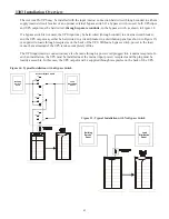
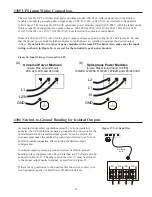
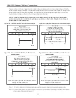
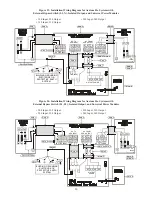
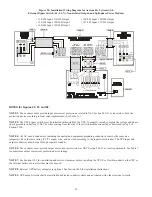
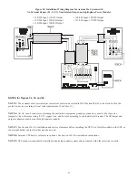
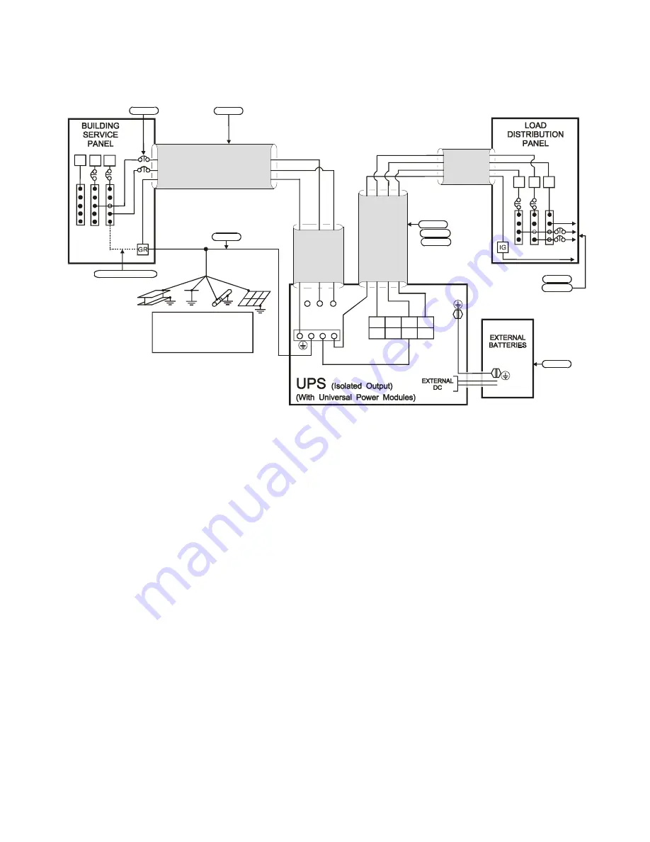
Figure 31: Installation Wiring Diagram for Axxium Pro Systems with
No External Bypass (L1, L2, N), Isolated Output, and Universal Power Modules
• 220 Input, 220 Output
• 240 Input, 240 Output
• 230 Input, 230 Output
BUILDING GROUNDING
ELECTRODE OR
PROTECTIVE EARTH
SYSTEM
L2
N L1
X1 X3 X0 X2
Note 3
Per Local Code
Note 1
Note 4
TO
LOADS
Note 4
Note 9
1
3
LINE INPUT
OUTPUT
POWER
2
Note 8
Note 6
Note 9
L2
N
L1
Note 7
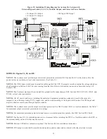
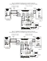
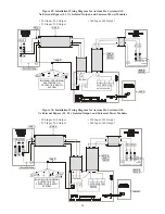
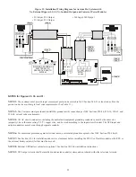
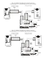
NOTES for Figures 29, 30, and 31:
NOTE 1: The customer must provide input overcurrent protection as stated in NEC Section 240-21 or local codes. Size the
protection device according to local code requirements. (See Table 11.)
NOTE 3: The Customer must provide and install this ground (earth) connection per NEC Sections 250-20, 250-30, 250-62, and
250-64, or local code requirements.
NOTE 4: All AC circuit conductors, including the neutral and equipment grounding conductors, must be the same size
(ampacity), have the same rating (75 ºC) copper wire, and be sized according to the input circuit breaker. The UPS input and
output conductors must be run through separate conduits.
NOTE 6: For maximum protection against electrical noise, use isolated ground receptacles. See NEC Section 250-146(d).
NOTE 7: See Section 1101 for installation and service clearances before installing the UPS. Use flexible conduit on the UPS or
the external battery cabinet if either must be moved.
NOTE 8: External UPS battery cabinets are optional. See Section 1400 for installation instructions.
NOTE 9: UPS output circuits shall be installed in dedicated conduit systems and not shared with other electrical circuits.

