
Service and Maintenance for Cylindrical Locks
5–22
W Series Service Manual
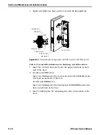
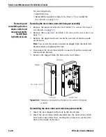
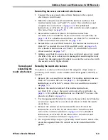
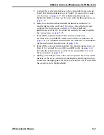
Task D. To remove the outside rose and liner assembly:
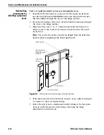
1. Slide the chassis assembly out of the door.
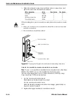
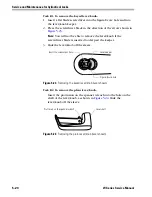
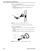
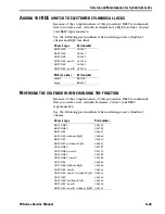
2. Retract the rose locking pin, and rotate the rose and liner assembly
counterclockwise until it is free from the hub.
3. Remove the rose and liner assembly from the sleeve.
Reinstalling
components for
electrified
cylindrical locks
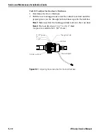
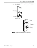
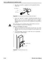
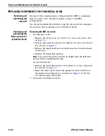
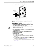
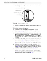
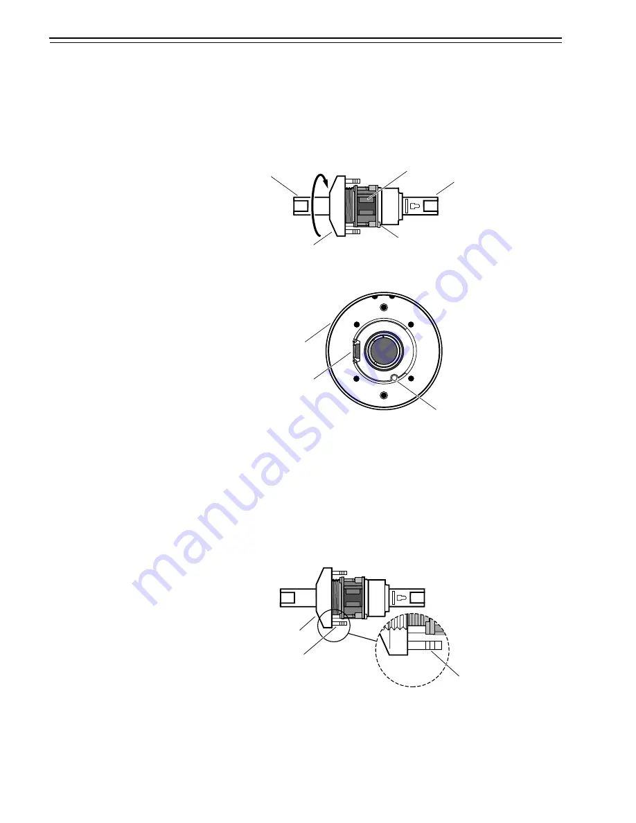
Task A. To reinstall the outside rose and liner assembly:
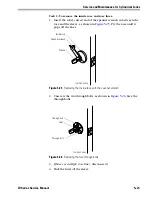
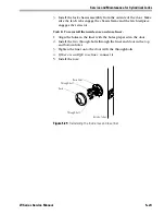
1. Retract the rose locking pin, and rotate the rose and liner assembly
clockwise until the proper door thickness groove on the
through-bolt stud lines up with the hub face.
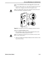
2. Release the rose locking pin. It should lock into the rose liner.
Figure 5.27
Removing the outside rose and liner assembly
Sleeve
Rose and liner assembly
Rose locking pin
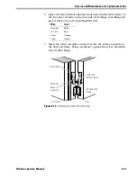
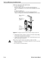
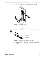
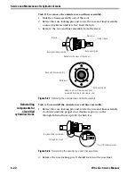
Retractor-side view of the chassis
Retractor
Inside sleeve
Head-on view of the rose and liner
assembly from the inside sleeve side
Rose locking pin
Retractor
Rose and liner assembly
Figure 5.28
Reinstalling the outside rose and liner assembly
Rose and liner assembly
Through-bolt stud
Door thickness grooves
Summary of Contents for 34HW
Page 1: ......
Page 6: ...Contents vi W Series Service Manual...
Page 38: ...IDH Max Locks Functions and Parts 2 24 W Series Service Manual...
Page 54: ...Electrified Locks Functions and Parts 3 16 W Series Service Manual...
Page 140: ...Service and Maintenance for Cylindrical Locks 5 30 W Series Service Manual...
Page 158: ...Additional Service and Maintenance for IDH Max Locks 6 18 W Series Service Manual...
Page 162: ...Glossary A 4 W Series Service Manual...
Page 164: ...Installation Instructions B 2 W Series Service Manual...