Complete system - Technical data
10
Data sheet V1.40 4XP0000.00-K64
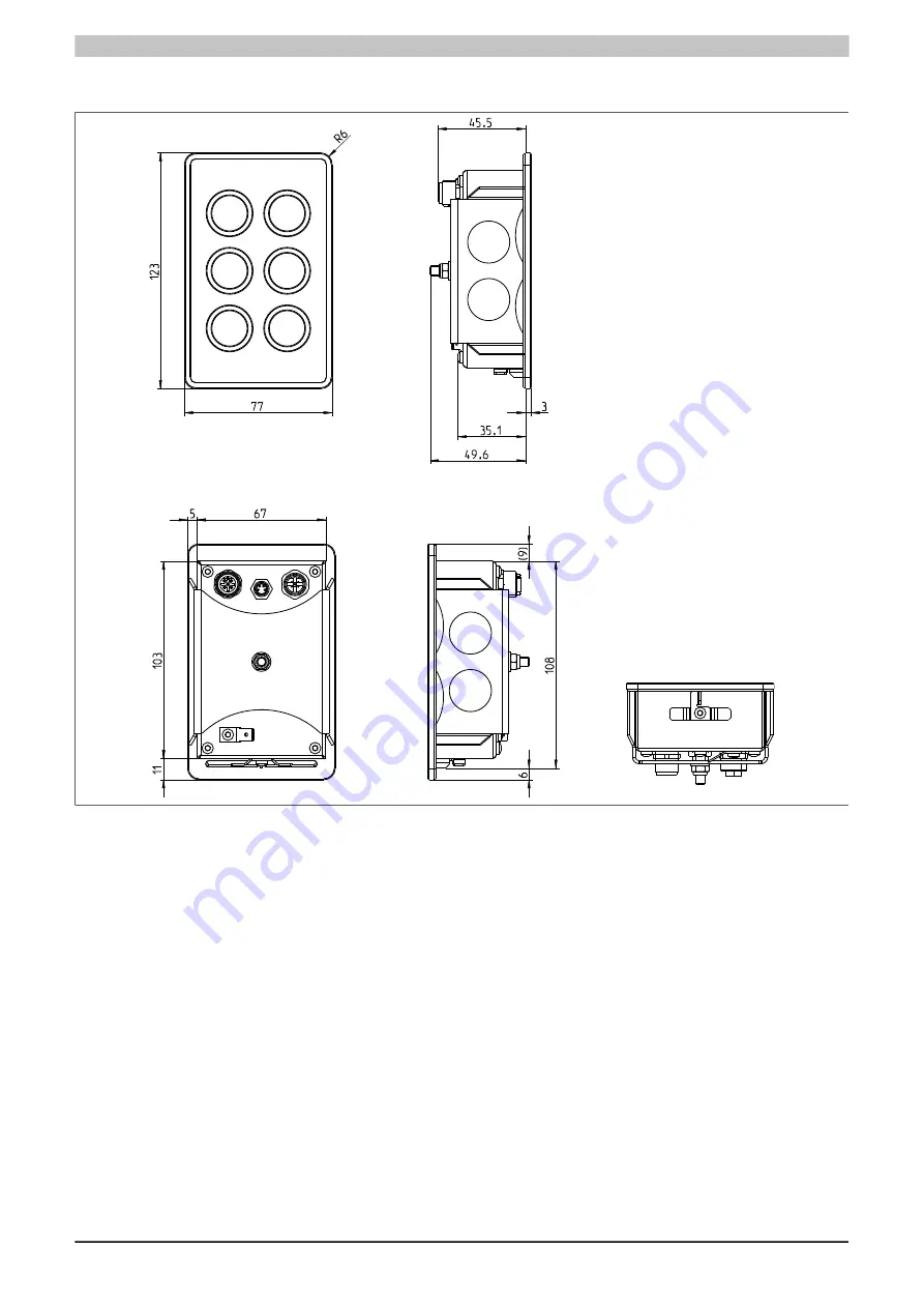
3.3 Dimensions
Figure 4: 4XP0000.00-K64 - Dimensions
Page 1: ...of publication however Bernecker Rainer Industrie Elektronik Ges m b H makes no warranty ex pressed or implied with regard to the products or documentation contained within this manual In addition Be...
Page 2: ...6 1 Slide in label design 13 3 7 Device label 14 3 8 Key and LED configuration 15 4 Safety guidelines 16 4 1 Intended use 16 4 2 Protection against electrostatic discharge 16 4 2 1 Packaging 16 4 2 2...
Page 3: ...Views Data sheet V1 40 4XP0000 00 K64 3 1 Views Figure 1 4XP0000 00 K64 Oblique view...
Page 4: ...Views 4 Data sheet V1 40 4XP0000 00 K64 Figure 2 4XP0000 00 K64 Rear view...
Page 5: ...ted ring keys 4 color green yellow red white IP65 protection fast mounting using single screw connection made using M8 M12 circular connec tors Table 1 4XP0000 00 K64 Order data 2 1 1 Description 4XP0...
Page 6: ...e safety guidelines and notices can result in injury or damage to property Information This information is important for preventing errors Table 3 Organization of safety notices 2 3 Guidelines E Europ...
Page 7: ...nterface X2X IN OUT M12 connectors X2X IN Pin Description 1 X2X 2 X2X 3 X2X 4 X2X X2X OUT Pin Description 1 X2X 2 X2X 3 X2X 4 X2X Table 5 X2X IN OUT M12 connectors Information The connector s pin assi...
Page 8: ...ly modules with an X2X Link power supply 3 1 3 Functional ground A functional grounding clip is located next to the power supply connector This grounding clip functional ground must be connected to a...
Page 9: ...320 mA at nominal voltage Operating conditions EN 60529 protection Front IP65 Back IP65 UL 50 protection Front Type 4X indoor use only Environmental conditions Temperature Operation 0 to 50 C Storage...
Page 10: ...Complete system Technical data 10 Data sheet V1 40 4XP0000 00 K64 3 3 Dimensions Figure 4 4XP0000 00 K64 Dimensions...
Page 11: ...imensions for cutout installations These devices are best installed in a cutout using the mounting clips on the housing or clamping blocks various designs possible 4 69 4 8 110 5 Cutout dimensions 110...
Page 12: ...ata 12 Data sheet V1 40 4XP0000 00 K64 3 5 Installation guidelines Mount the device in the cutout using the mounting bracket and an M5 Durlok nut maximum torque 1 2 Nm Max 1 2 Nm Figure 6 4XP0000 00 K...
Page 13: ...anslucent white B R 017 Colors matched to provided color sample Transparent Unprinted Figure 7 4XP0000 00 K64 Panel overlay design 3 6 1 Slide in label design Important This image is not a true repres...
Page 14: ...64 3 7 Device label This label is attached to the back as a way to identify the interfaces C0036464 02 X2X IN X2X OUT POWER SUPPLY X2X IN X2X OUT 4 1 2 3 Pin POWER SUPPLY 24 V DC GND 24 V DC GND X2X X...
Page 15: ...Complete system Technical data Data sheet V1 40 4XP0000 00 K64 15 3 8 Key and LED configuration Figure 10 4XP0000 00 K64 Key and LED matrix...
Page 16: ...th a housing Electrical components without a housing are protected by ESD suitable packaging 4 2 2 Guidelines for proper ESD handling Electrical components with a housing Do not touch the connector co...
Page 17: ...on voltage to the control cabinet must be switched off and prevented from being switched on again General safety guidelines and national accident prevention regulations must be observed Electrical ins...
Page 18: ...friendly disposal All B R programmable controllers operating monitoring devices and uninterruptible power supplies are designed to inflict as little harm as possible on the environment 4 7 1 Separatio...
Page 19: ...carbons Toluene Xylene White spirits Trichloroethane Ethyl acetate Diethyl ether n Butyl acetate Amyl acetate Butylcellosolve Ether Acetone Methyl ethyl ketone Dioxan Cyclohexanone Methylisobutylketon...
Page 20: ...K64 Device interfaces 7 Figure 4 4XP0000 00 K64 Dimensions 10 Figure 5 4XP0000 00 K64 Cutout installation 11 Figure 6 4XP0000 00 K64 Installation guidelines 12 Figure 7 4XP0000 00 K64 Panel overlay de...
Page 21: ...K64 Order data 5 Table 2 Version information 5 Table 3 Organization of safety notices 6 Table 4 Range of nominal sizes 6 Table 5 X2X IN OUT M12 connectors 7 Table 6 Power supply 7 Table 7 4XP0000 00...