


21.12.98
Operating manual
04_GB
ACP 3000 — 0.37–15.0
29
Berges electronic
•
D–51709 Marienheide-Rodt
•
Tel. 02264/17-0
•
Fax 02264/17126
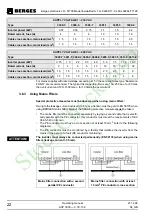
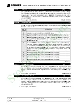
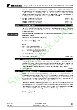
3.16
J20 Configuration
Jumpers J20, on the bottom left edge of the control module (see Figures 3.4–3.6), enable
changeover of analog value specification and the switching logic of the digital control inputs.
It has seven (7) positions and two movable shorting jumpers. One jumper selects the ana-
log speed reference used and the second jumper selects the active state (High or Low) of
the digital inputs. A pair of small needle nose pliers will prove useful for moving these jump-
ers. REMOVE AC POWER AND WAIT FOR ALL INDICATORS TO GO OUT BEFORE
CHANGING THIS JUMPERS.
JUMPER
SETTINGS
FUNCTION
DESCRIPTION
VIN1: 0–10 VDC Terminal input VIN1:
This configures the drive to accept an external 0–10 VDC speed reference sig-
nal.
24-FSEL
selects direct or inverse operation. Input impedance is 95 k
Ω
.
VIN1: 0–20 mA
or 4–20 mA
Terminal input VIN1:
This configures the drive for either a 0–20 mA or a 4–20 mA input from an exter-
nal source. 0–20 mA or 4–20 mA is selected by
24-FSEL
. Input impedance is
250 k
Ω
.
VIN1: 0–5 VDC
Terminal input VIN1:
(DEFAULT SETTING) This configures the drive for an external 0–5 VDC signal,
or a speed potentiometer powered from the REF terminal on the control terminal
strip.
24-FSEL
selects direct or inverse operation. Input impedance is 48 k
Ω
.
VIN2: 0–10 VDC Terminal input VIN2:
This configures the drive to accept an external 0–10 VDC speed reference sig-
nal.
24-FSEL
selects direct or inverse operation. Input impedance is 95 k
Ω
.
VIN2: 0–5 VDC
Terminal input VIN2:
This configures the drive for an external 0–5 VDC signal, or a speed potentiom-
eter powered from the REF terminal on the control terminal strip.
24-FSEL
se-
lects direct or inverse operation. Input impedance is 48 k
Ω
.
Pull-Down Logic This configures the digital inputs for pull-down logic. That is, active when con-
nected to terminal CM. Inputs are high, and are pulled low to activate.
Pull-Up Logic
(DEFAULT SETTING)
This configures the digital inputs for pull-up logic. That is, active when connected
to terminal V+, or to an external power supply with it's common connected to CM.
Inputs are low and require a positive voltage to activate them. 0 to 3 VDC is IN-
ACTIVE, 10 to 24 VDC is ACTIVE.
StockCheck.com


