BenQ DH550C, User Manual
The BenQ DH550C is a high-quality projector that delivers crisp, clear images. Easily set up and operate the device with the included User Manual. For a free download of the manual, visit manualshive.com. Enhance your viewing experience with this user-friendly and efficient projector.
Share
Download


Reviews:
No comments
Related manuals for DH550C

PS-42P4H
Brand: Samsung Pages: 13
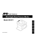
UB-511
Brand: A&D Pages: 16
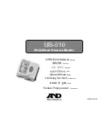
UB-510
Brand: A&D Pages: 50
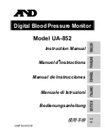
UA-852
Brand: A&D Pages: 20
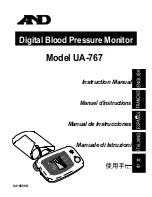
UA-767
Brand: A&D Pages: 14
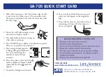
UA-705
Brand: A&D Pages: 3

UA-621
Brand: A&D Pages: 42

UA-1030T
Brand: A&D Pages: 2
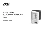
ESSENTIAL UB-525
Brand: A&D Pages: 48

S19C150F
Brand: Samsung Pages: 95

OH46D
Brand: Samsung Pages: 2

OH46F
Brand: Samsung Pages: 2

SyncMaster 570S TFT
Brand: Samsung Pages: 30

SAMTRON 76E
Brand: Samsung Pages: 45

S24C230BL
Brand: Samsung Pages: 79

S27B970D
Brand: Samsung Pages: 70

SyncMaster BN59-00954A_02
Brand: Samsung Pages: 21

SyncMaster BX2035
Brand: Samsung Pages: 47


