background image


Product Service Manual – Level 2 

Service Manual for BenQ: 
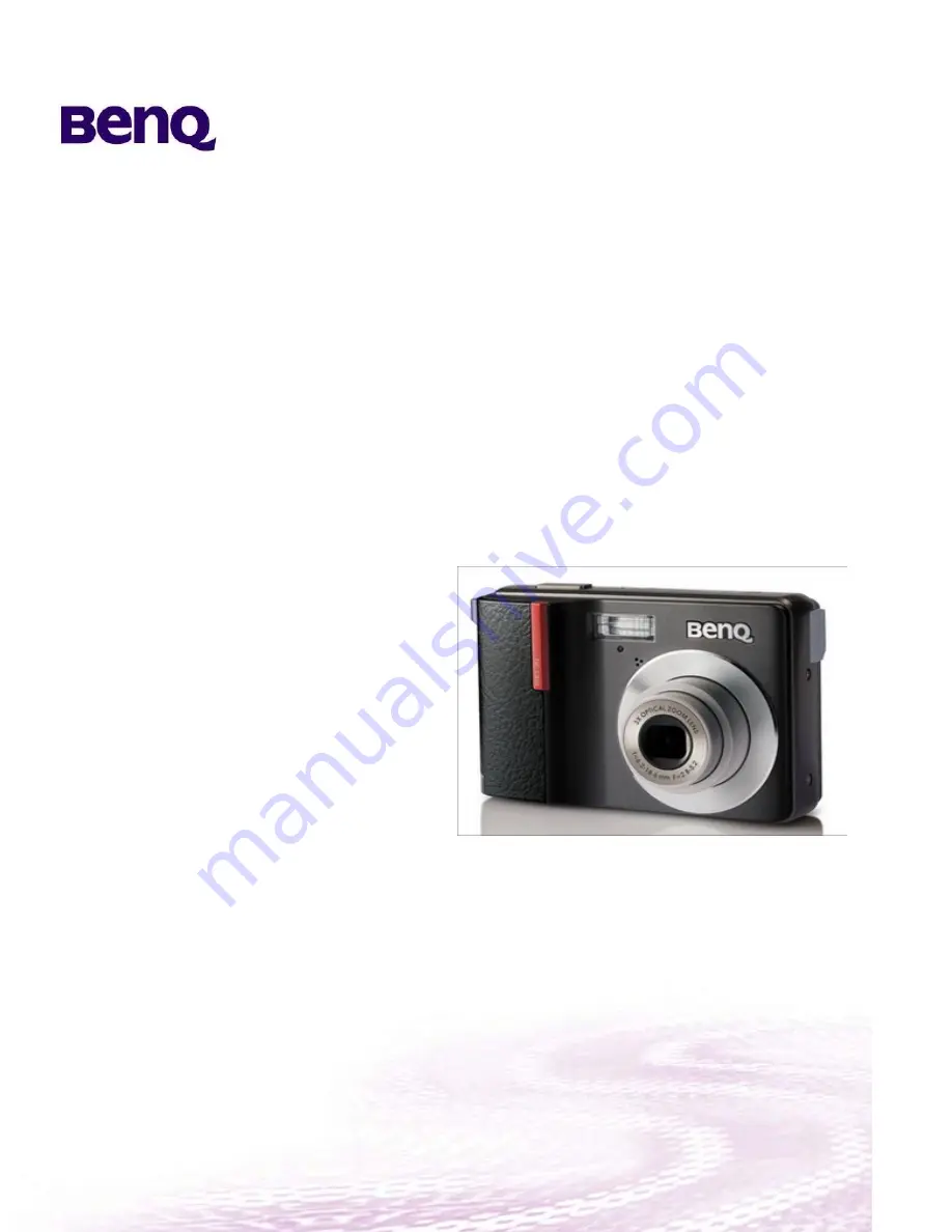
DC C850 
P/N: 9H.T8867.9AX 
 
 
Applicable for All Regions 


Version: 001a 
Date:

2008/

3

/

3

1


Notice: 
- For RO to input specific “Legal Requirement” in specific NS regarding to responsibility and liability statements. 
 
- Please check BenQ’s eSupport web site, http://esupport.benq.com, to ensure that you have the most recent version of 
this manual.


First Edition (

March

, 2008) 

© Copyright BenQ Corporation 2008. All Right Reserved.


Summary of Contents for DC C850

Page 1: ...2008 3 31 Notice For RO to input specific Legal Requirement in specific NS regarding to responsibility and liability statements Please check BenQ s eSupport web site http esupport benq com to ensure that you have the most recent version of this manual First Edition March 2008 Copyright BenQ Corporation 2008 All Right Reserved ...

Page 2: ...fety Notice 4 General Descriptions 4 Related Service Information 4 Product Overview 4 Level 1 Specification Packing 4 Specification 5 Packing 6 Level 2 Disassembly Assembly Flow Calibration Procedure 10 Disassembly Assembly Flow 10 Exploded View 18 Calibration Procedure 24 Trouble Shooting Guide 32 Abbreviations Acronyms ...

Page 3: ...cs tests troubleshoot problems and align the BenQ product Trademark The following terms are trademarks of BenQ Corporation BenQ Importance Only trained service personnel who are familiar with this BenQ Product shall perform service or maintenance to it Before performing any maintenance or service the engineer MUST read the Safety Note ...

Page 4: ...nd meets all government safety requirements 2 Ensure that other persons are safe while you are servicing the product 3 DO NOT perform any action that may cause a hazard to the customer or make the product unsafe 4 Use proper safety devices to ensure your personal safety 5 Always use approved tools and test equipment for servicing 6 Never assume the product s power is disconnected from the mains po...

Page 5: ... Cloudy Tungsten Fluorescent H Fluorescent L MWB Exposure 2 2 EV 0 3EV step ISO Auto 50 100 200 400 800 1600 Flash Auto Red eye reduction Forced on Slow sync Forced off Self Timer 2 sec 10 sec 10 2 sec Power Source AA Battery x 2 Alkaline Li Ion Oxyride or NiMH Storage Type Built in 16 MB Usable 6MB SD SDHC card compatible File Format Still Image JPEG EXIF 2 2 compatible DCF compatible Support DPO...

Page 6: ...2 Back LCD with protective film VG0692533620191 1EA 3 Top 4 Camera sides Printing DC C850 8 0 MEGA PIXELS Printing DC C850 8 0 MEGA PIXELS 5 Bottom safety regulation label VG0692104650090 6 POP VG0692134020191 protective film VG0692534630090 8 0 MEGA PIXELS ...

Page 7: ...hened by hand 9 Bag Pearl bag VG0692501980090 10 Color box VG0692414650090 11 Separtator VG0692433640092 Address label VG069213ZBC9091 12 SN label VG069213ZBC0090 13 Battery VG0376210800003 14 USB cable VR0592913530000 Wrist band VG0692183240091 AV cable VR0592944070000 Battery USB cable Wrist band AV cable ...

Page 8: ...G0692313070190 17 Spanish warranty card VG0692313070490 18 Warranty card VG0692313070391 Printing DC C750 C850 19 Accessory 20 Accessory in PE bag VG069250Z200002 UM back sealed with transparent tape 21 USB cable AV cable wrist band battery camera bag 22 Camera in color box ...

Page 9: ...iton 25 Color box seal label VG0692131332090 26 2 yr warranty label VG0692131431090 27 Color box entering carton VG0692443070092 28 Seal label VG069213ZBC4090 29 Outer carton label Position 30 Outer carton label VG069213ZBC5090 Seal label on top and bottom 此圖為代用 ...

Page 10: ...low Calibration Procedure Disassembly Assembly Caution 1 Prevent cosmetic issue please clean the table when disassemble 2 Wear anti static bracelet for ESD 1 Remove the front back cover 1 a Unscrew the screws of front and back cover ...

Page 11: ...1 b Remove the back cover 1 c Remove the front cover ...

Page 12: ...2 Disassemble the main body of camera Noted Discharge the capacitor of flash board in advance before disassembling it to avoid any damage Discharger ...

Page 13: ...2 a Disassemble LCD panel Disassemble LCD panel from 6 joints of metal plate as below 2 b Remove the black mylar and loose FPC cable ...

Page 14: ...2 c Disassemble Strobe flash board Remove mylar Unscrew the screws ...

Page 15: ... Unsolder the connection of main board and strobe board 3 Unsolder the battery spring 2 d Disassemble M B 1 Unscrew the screws 2 Clean the solder of CCD pin 4 Loose the FPC cable ...

Page 16: ...2 e Disassemble the Lens assembly and battery cover Unscrew the screws ...

Page 17: ...Rear Cover Front Cover Strobe Board Mainboard LCD Panel Lens Assembly Battery Cover Frame Exploded View ...

Page 18: ......

Page 19: ......

Page 20: ......

Page 21: ......

Page 22: ......

Page 23: ......

Page 24: ...01 Press Tele OK Playback to power on 02 Check FW version on the upper right corner B How to update FW by using SD card 01 Make sure the battery is full 02 Format SD card and copy FW into SD card 03 Press Right Power key to power on C F W update replace M B 1 Start the F W testing program FRM and check the following setting is correct or not Fig 1 ISP Button Fig 1 ...

Page 25: ...sure the current is less than 0 01A 4 Press Power button of camera Fig 2 to power on and press ISP button to update F W 5 Press OK button Fig 3 when the dialogue box showed Program All Finished 6 The camera will be power off automatically and ensure the current is under 0 01A Then remove the special cable F W programming cable Set Playback Power Fig 2 Fig 3 ...

Page 26: ...he test was failed 7 The on screen display shows the Meshut 26 message Fig 9 Put the camera in front of the light source box about 35mm and adjust the LV value to LV 12 according to the instruction 8 Tap OK button and then press Set button Calibration program will execute automatically 9 When the on screen display shows OK Fig 10 it means the test is passed If it shows NG it means the test was fai...

Page 27: ... FW version Fig 5 Fig 6 Fig 7 Fig 8 Fig 9 Fig 10 ...

Page 28: ...ution 1 Voltage setting 3 0 0 1V 2 Light source box brightness K 1 3 LV 10 0 0 1 Color temperature 5500K LV 12 0 0 1 LV 14 0 0 1 LV value is based on the BM3000 measurement data 3 Brightness Center 250 30CD M2 Peripheral 300 30CD M2 ...

Page 29: ...t button the test program will execute automatically 4 The on screen display shows OK Fig 16 once the test is passed If it shows NG it means the test was failed 5 The on screen display shows Light S S message Fig 17 Put the camera in front of light source box around 35 mm 6 Tap OK button and press Set button the test program will execute automatically 7 The on screen display shows OK Fig 18 once t...

Page 30: ...g 20 G Focus Capture and Video Capture 1 Insert TV cable into USB slot and put camera on the fixture Press Power to power it on Fig 21 2 Press Menu button click left button and select setup Fig 22 3 Select TV out and set NTSC PAL PAL NTSC to see the display is color Fig 23 4 Press Menu button to go back Press playback button to check the time setting is correct Press playback to access preview mod...

Page 31: ...Set Playback Power Fig 21 Fig 22 Fig 23 Caution 1 Voltage setting 3 0 0 1V 2 Light source box brightness Center 250 30CD M2 Peripheral 300 30CD M2 ...

Page 32: ...formation dirty poor soldering of the spring of battery II Check the soldering of battery s spring of M B 2 Check the connection of each PCB 01 Check the connection between M B and ST B 02 Check the connection between M B and LCD 03 Check the connection between M B and LENS 3 Current 0mA when power on 01 Check U12 voltage output if it is abnormal please analyze its circuit 02 Check the fuse is ope...

Page 33: ...7VCCD is within this range 02 Check the peripheral components and U1 03 Check the peripheral components and CCD board 4 TV display abnormal 01 Check the function J6 of M B 02 Check the connection between U1 and other components 5 Power LED is on but LENS still doesn t work 01 Check the connection between J3 of M B and LENS FPC 02 Check the LENS is OK or not 03 Ensure the output voltage of U12 is V...

Page 34: ...pheral components 2 Still charge when switch to strobe mode 01 Check the function and soldering of U1 R5 and R4 of ST B 02 Check the soldering between ST B and M B 3 Can t Flash 01 Check the soldering between ST B and M B 02 Check the function and soldering of U1 TR1 Q1 and flash light Flash light SW1 Q1 U1 T1 TR1 C5 ...

Page 35: ... BGA with good soldering III Make sure the peripheral components of BGA are in good condition 02 Can t record I Check the MIC function II Check the BGA with good soldering 03 Cannot read write from SD card I Check function of SD card II Check the SD slot socket with good soldering III Check the soldering of SD slot socket circuit ...

Reviews: