background image

09/ 2013 


BENNING MM 2


D


 F E   I     S 

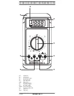
Bild 1: 

Gerätefrontseite

Fig. 1: 

Front tester panel

Fig. 1: 

Panneau avant de l'appareil

Fig. 1: 

Parte frontal del equipo

Obr.1:  

Přední strana přístroje

σχήμα 1:   Μπροστινή όψη

ill. 1: 

Lato anteriore apparecchio

Fig. 1:  

Voorzijde van het apparaat

Rys.1:  

Panel przedni przyrządu

Imaginea 1:  Partea frontală a aparatului

Рис. 1. 

Фронтальная сторона прибора

Fig. 1: 

Instrumentfront

Resim 1:  Cihaz ön yüzü

Summary of Contents for MM 2

Page 1: ...eitung Operating manual F Mode d emploi E Manuel de instrucciones N vod k obsluze I Istruzioni per l uso Gebruiksaanwijzing Instrukcja obs ugi Instructiuni de folosire S Bruksanvisning Kullanma Talima...

Page 2: ...D Bedienungsanleitung Operating manual F Mode d emploi Gebruiksaanwijzing BENNING MM 2 Mehrsprachige Anleitung auf beigef gter CD und unter www benning de Multilingual manuals on included CD and at...

Page 3: ...el Fig 1 Panneau avant de l appareil Fig 1 Parte frontal del equipo Obr 1 P edn strana p stroje 1 ill 1 Lato anteriore apparecchio Fig 1 Voorzijde van het apparaat Rys 1 Panel przedni przyrz du Imagin...

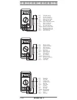
Page 4: ...urement Fig 3 Mesure de tension alternative Fig 3 Medici n de tensi n alterna Obr 3 M en st dav ho nap t 3 AC ill 3 Misura tensione alternata Fig 3 Meten van wisselspanning Rys 3 Pomiar napi cia przem...

Page 5: ...g 6 Medici n de resistencia Obr 6 M en odporu 6 ill 6 Misura di resistenza Fig 6 Weerstandsmeting Rys 6 Pomiar rezystancji Imaginea 6 M surarea rezisten ei 6 Fig 6 Resistansm tning Resim 6 Diren l m B...

Page 6: ...ur Fig 8 Control de continuidad con vibrador Obr 8 Zkou ka pr chodu bzu kem 8 ill 8 Prova di continuit con cicalino Fig 8 Doorgangstest met akoestisch signaal Rys 8 Pomiar ci g o ci obwodu Imaginea 8...

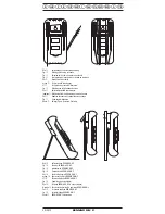
Page 7: ...lui BENNING MM 2 12 BENNING MM 2 Fig 12 Att st lla h nga BENNING MM 2 Resim 12 BENNING MM 2 nin kurulumu Bild 11 Aufwicklung der Sicherheitsmessleitung Fig 11 Winding up the safety test leads Fig 11 E...

Page 8: ...gesehen und darf nicht in Stromkreisen mit einer h heren Nennspannung als 1000 V DC und 750 V AC eingesetzt werden N heres hierzu im Abschnitt 6 Um ge bungs be din gungen In der Bedienungsanleitung un...

Page 9: ...t das Ger t au er Betrieb zu setzen und gegen unbeabsichtigten Betrieb zu sichern Es ist anzunehmen dass ein gefahrloser Betrieb nicht mehr m glich ist wenn das Ger t oder die Messleitungen sichtbare...

Page 10: ...rie 5 1 11 Ger teabmessungen L x B x H 175 x 84 x 31 mm ohne Gummi Schutzrahmen L x B x H 192 x 95 x 50 mm mit Gummi Schutzrahmen Ger tegewicht 340 g ohne Gummi Schutzrahmen 550 g mit Gummi Schutzrahm...

Page 11: ...n Zeit 30 Sekunden Pause 3 Minuten 10 A dauernd Messbereich Aufl sung Messgenauigkeit Spannungsabfall 200 A 0 1 A 1 0 des Messwertes 2 Digit 600 mV max 2 mA 1 A 1 0 des Messwertes 2 Digit 600 mV max 2...

Page 12: ...BENNING MM 2 k nnen zu instabiler An zeige und zu Messfehlern f hren 8 2 Spannungs und Strommessung Maximale Spannung gegen Erdpotential beachten Elektrische Gefahr Die h chste Spannung die an den Buc...

Page 13: ...itungen mit den Messpunkten kontaktieren Unter schreitet der Leitungswiderstand zwischen der COM Buchse und der Buchse f r V 50 ert nt im BENNING MM 2 der eingebaute Summer siehe Bild 8 Durchgangspr f...

Page 14: ...atterien bzw Sonderm ll abgegeben werden Informieren Sie sich bitte bei Ihrer Kommune 9 4 Sicherungswechsel Vor dem ffnen den BENNING MM 2 unbedingt spannungsfrei machen Elektrische Gefahr Das BENNING...

Page 15: ...esung oder aufzu h ngen siehe Bild 12 Der Gummi Schutzrahmen besitzt eine se die f r eine Auf h nge m g lichkeit genutzt werden kann siehe Bild 11 Aufwicklung der Sicherheitsmessleitung siehe Bild 12...

Page 16: ...is designed for measuring in dry conditions and must not be used on electrical circuits with a rated voltage greater than 1000 V DC and 750 V AC for details refer to Ambient Conditions section The fo...

Page 17: ...ble signs of damage or if the multimeter no longer functions or after long periods of storage under unfavourable conditions or after being subjected to rough transport In order to avoid danger do not...

Page 18: ...covered with protective caps 5 1 13 The BENNING MM 2 is protected from mechanical damage by a pro tective rubber holster The protective rubber holster allows the BENNING MM 2 to be placed upright or h...

Page 19: ...age sensing and is displayed as the RMS value Overload protection 1 A 500 V fast blow fuse on A mA input terminal 16 A 500 V fast blow fuse on 20 A input terminal Current measurements in the 20 A rang...

Page 20: ...ent Select the appropriate range and voltage type with the rotary switch of the BENNING MM 2 Connect the black safety test lead to the COM terminal of the BENNING MM 2 Connect the red safety test lead...

Page 21: ...lectrotechnical personnel who must take special precautionary measures to avoid accidents This is how to ensure that the BENNING MM 2 is free from any voltage before the instrument is opened first rem...

Page 22: ...ear the input terminals until it gently unsnaps from the case front at the end nearest to the LCD display Do not remove any screws from the printed circuit board of the BENNING MM 2 Lift the printed c...

Page 23: ...ve class II continuous double or reinforced insulation Contamination class 2 Length 1 4 m AWG 18 Environmental conditions Maximum barometric elevation for making measurements 2000 m Temperatures 0 C t...

Page 24: ...con u pour proc der des mesures dans un environne ment sec et ne doit pas tre utilis dans des circuits lectriques dont la tension nominale est sup rieure 1000 V CC et 750 V CA pour plus d information...

Page 25: ...us possible il faut mettre l appareil hors service et le prot ger contre toute utilisation involontaire Une utilisation sans risques n est plus possible quand l appareil ou les c bles de mesure pr sen...

Page 26: ...appareil L x B x H 175 x 84 x 31 mm sans cadre de protection en caoutchouc L x B x H 192 x 95 x 50 mm avec cadre de protection en caoutchouc Poids de l appareil 340 g sans cadre de protection en caou...

Page 27: ...tion rapide l entr e 20 A Les mesures de courant dans la plage de 20 A doivent tre br ves dur e 30 secondes pause 3 minutes et continues dans la plage de 10 A Plage de mesure R solution Pr cision de m...

Page 28: ...cteur des c bles de mesure de s curit il faudra remplacer imm diatement les c bles de mesure de s curit Avant de S lectionnez une autre fonction avec le commutateur rotatif il faut retirer les c bles...

Page 29: ...t dans la diode l affichage 1 indique qu il y a une interruption dans la diode Dans le cas d une diode plac e dans le sens de non conduction l affichage 1 appara t Si la diode est d fectueuse 000 ou u...

Page 30: ...mentation et placez les de telle sorte qu ils ne soient pas comprim s entre les parties du bo tier Placez ensuite la pile dans le compartiment pr vu cet effet dans la partie avant Assemblez le fond du...

Page 31: ...ibre pour tre dirig e vers un point de mesure avec le BENNING MM 2 L trier au dos du cadre de protection en caoutchouc permet d incliner pour en faciliter la lecture ou de suspendre le BENNING MM 2 vo...

Page 32: ...t cniamente instru das El BENNING MM 2 est dise ado para medici n en ambiente seco no pudi ndose emplear en circuitos el ctricos con una tensi n nominal superior a los 1000 V DC y 750 V AC ver punto C...

Page 33: ...o sin peligro hay que desactivar el equipo y asegurarlo para evitar su accionamiento involuntario Se supone que ya no queda garantizado su funcionamiento sin peligro cuando el equipo o las conduccione...

Page 34: ...84 x 31 mm sin marco protector de goma L x A x alt 192 x 95 x 50 mm con marco protector de goma Peso del equipo 340 g sin marco protector de goma 550 g con marco protector de goma 5 1 12 Las conducci...

Page 35: ...duraci n tiempo 30 segundos pausa 3 minutos 10 A cont nuo rango de medici n resoluci n exactitud de medici n ca da de tensi n 200 A 0 1 A 1 0 del valor medido 2 d gitos 600 mV max 2 mA 1 A 1 0 del val...

Page 36: ...ionar otra funci n mediante el conmutador disco hay que separar las conexiones protegidas de medici n del punto de medici n Fuentes de fuerte interferencia en las inmediaciones del BENNING MM 2 pueden...

Page 37: ...diodo se indica 000 u otros valores ver fig 7 Verificaci n de diodos 8 5 Control de continuidad con vibrador Mediante el conmutador disco seleccionar la parte marcada con el s mbolo de vibrador y dio...

Page 38: ...dentro del marco protector de goma ver fig 9 Cambio de bater a Aporte su granito a la protecci n del medio ambiente Las pilas no son basura dom stica Se pueden entregar en un punto de colecci n de pi...

Page 39: ...colocaci n inclinada del BENNING MM 2 facilita la lectura o colgarlo ver fig 12 El marco protector de goma dispone de un ojal que puede servir para colgarlo ver fig 11 Arrollamiento de la conducci n p...

Page 40: ...ro m en v such m prost ed Nesm se pou vat v proudov ch obvodech s jmenovit m nap t m vy m ne 1000 V DC a 750 V AC Bli informace najdete v kapitole 6 Podm nky prost ed V n vodu k obsluze a na p stroji...

Page 41: ...po dlouh m skladov n v nevyhovuj c ch podm nk ch po obt n p eprav Pro vylou en ohro en nedot kejte se hol ch pi ek m c ho veden zasouvejte m c veden do odpov daj c ch z suvek v multimetru 3 Rozsah do...

Page 42: ...roud p stroje BENNING MM 2 5 1 13 P stroj BENNING MM 2 je chr n n p ed mechanick m po kozen m pry ov m ochrann m r mem 9 Pry ov ochrann r m 9 umo uje p stroj b hem m en postavit nebo pov sit 6 Podm nk...

Page 43: ...dnota se z sk v zpr m rov n m a zobrazuje se jako efektivn hodnota Ochrana p ed p et en m F 1 A 500 V ji t n rychl A mA na na vstupu F 16 A 500 V ji t n rychl 20 A na vstupu M en proudu v rozsahu 20 A...

Page 44: ...doj t k po kozen p stroje Po kozen p stroj m e b t p i dal m u v n nebezpe n 8 2 1 M en nap t Pomoc oto n ho sp na e 4 zvolte na p stroji BENNING MM 2 po adova nou funkci ern bezpe nostn kabel m ic ho...

Page 45: ...ebezpe razu elektrick m proudem Pr ci na otev en m p stroji BENNING MM 2 pod nap t m sm j prov d t v hradn kvalifikovan elektrik i kte p itom musej prov d t zvl tn opat en pro prevenci raz P ed otev e...

Page 46: ...ou zabudovanou pojistkou 16 A rychl viz obr 10 Takto vym n te pojistky odpojte oba m c kabely od m en ho objektu odpojte oba m c kabely od p stroje BENNING MM 2 oto n m sp na em 4 zvolte funkci OFF se...

Page 47: ...r zek 12 Postaven p stroje BENNING MM 2 11 Technick daje m c ho p slu enstv norma EN 61010 031 maxim ln m en nap t proti zemi a m c kategorie s n str nou epi kou 1000 V CAT III 600 V CAT IV bez n str...

Page 48: ...09 2013 BENNING MM 2 41 BENNING MM 2 1 2 3 4 5 6 7 8 BENNING MM 2 9 10 BENNING MM 2 11 12 1 BENNING MM 2 1000 V 750 V 6 BENNING MM 2 BENNING MM 2 BENNING MM 2 II BENNING MM 2 DC AC...

Page 49: ...BENNING MM 2 1000 V II 600 V III 4 mm III CAT III CAT IV 30 V AC 60 V DC m 3 BENNING MM 2 3 1 BENNING MM 2 3 2 M 1 4 m 3 3 1 4 m 3 4 3 5 3 6 9V 3 7 BENNING MM 2 16 A 500 V 6 35 mm 32 mm 749770 1 500 V...

Page 50: ...M 2 30 4 5 1 7 0 15 x C 18 C 28 C 23 C 5 1 8 BENNING MM 2 9 V IEC 6 LR 61 5 1 9 5 1 10 300 5 1 11 x x 175 x 84 x 31 mm M x x Y 192 x 95 x 50 mm 340 gr 550 gr 5 1 12 BENNING MM 2 5 1 13 BENNING MM 2 9...

Page 51: ...1 3 5 500 V DC 350 V AC 2 V 1 mV 1 3 5 1200 V DC 850 V AC 20 V 10 mV 1 3 5 1200 V DC 850 V AC 200 V 100 mV 1 3 5 1200 V DC 850 V AC 750 V 1 V 1 3 5 1200 V DC 850 V AC 7 3 1 500 V mA 16 500 V 20 A 20...

Page 52: ...ax 7 5 500 Veff 200 0 1 0 8 4 2 5 mA 3 2 V 2 k 1 0 8 2 200 A 0 5 V 20 k 10 0 8 2 40 A 0 5 V 200 k 100 0 8 2 4 A 0 5 V 2 M 1 k 0 8 2 400 nA 0 5 V 20 M 10 k 2 5 40 nA 0 5 V 7 6 0 4 V 0 9 V 500 Veff R 50...

Page 53: ...2 2 4 BENNING MM 2 COM 6 BENNING MM 2 7 mA BENNING MM 2 200 mA 8 20 200 mA 20 1 BENNING MM 2 4 5 8 3 4 BENNING MM 2 COM 6 BENNING MM 2 y V 5 BENNING MM 2 1 BENNING MM 2 6 8 4 4 BENNING MM 2 COM 6 BEN...

Page 54: ...5 V BENNING MM 2 50 8 9 BENNING MM 2 BENNING MM 2 BENNING MM 2 2 BENNING MM 2 4 OFF 9 1 BENNING MM 2 BENNING MM 2 9 2 BENNING MM 2 9 3 BENNING MM 2 BENNING MM 2 9 V 9 3 A 2 BENNING MM 2 4 OFF 9 BENNI...

Page 55: ...BENNING MM 2 BENNING MM 2 3 1 BENNING MM 2 3 BENNING MM 2 9 10 9 5 Calibration calibration 9 6 F 16 A 500 V 6 35 mm 32 mm 749770 F 1 A 500 V 6 35 mm 32 mm 749669 10 9 9 11 9 BENNING MM 2 9 BENNING MM...

Page 56: ...09 2013 BENNING MM 2 49 1000 V CAT II 10 A II 2 1 4 m AWG 18 2000 m 0 C 50 C 50 80 12...

Page 57: ...e impiegato in circuiti con una tensione nominale superiore a 1000 V CC e 750 V CA per maggiori dettagli vedere la sezione 6 Condizioni ambientali Nelle istruzioni d uso e sul BENNING MM 2 vengono usa...

Page 58: ...o l apparecchio ed al sicuro da un esercizio non intenzionale da presumere che non sia pi possibile un esercizio sicuro se l apparecchio o i cavetti mostrano danni evidenti se l apparecchio non funzio...

Page 59: ...ttivo Lungh x largh x alt 192 x 95 x 50 mm con guscio protettivo Peso apparecchio 340 g senza guscio protettivo 550 g con guscio protettivo 5 1 12 I cavetti di sicurezza in dotazione sono espressament...

Page 60: ...secon di pausa 3 minuti nella portata 10 A continue Portata Risoluzione Precisione misure Calo di tensione 200 A 0 1 A 1 0 del valore misura 2 digit 600 mV max 2 mA 1 A 1 0 del valore misura 2 digit 6...

Page 61: ...isura Forti fonti di disturbo in prossimit del BENNING MM 2 possono causare indicazioni instabili ed errori di misura 8 2 Misure di tensione e corrente Osservare la tensione massima rispetto al potenz...

Page 62: ...vengono indicati 000 o altri valori Si veda ill 7 Prova diodi 8 5 Prova di continuit con cicalino Con la manopola 4 selezionare sul BENNING MM 2 il campo contrasse gnato col simbolo cicalino diodo In...

Page 63: ...revisto della parte anteriore Inserire a scatto il fondo dell involucro nella parte anteriore e riavvitare le tre viti Infilare il BENNING MM 2 nel guscio protettivo 9 Si veda ill 9 Sostituzione batte...

Page 64: ...ill 12 Il guscio protettivo 9 dispone di un asola che pu essere utilizzata per appendere l apparecchio Si veda ill 11 Avvolgimento dei cavetti di sicurezza Si veda ill 12 Posizionamento del BENNING M...

Page 65: ...n droge ruimtes en mag niet worden gebruikt in electrische circuits met een nominale spanning hoger dan 1000 V DC en 750 V AC zie ook pt 6 Gebruiksomstandigheden In de gebruiksaanwijzing en op de BENN...

Page 66: ...n gebruikt mag het dan ook niet meer worden ingezet maar zodanig worden opgeborgen dat het ook niet bij toeval niet kan worden gebruikt Ga ervan uit dat gebruik van het apparaat zonder gevaar niet mee...

Page 67: ...l benodigde spanning daalt ver schijnt het batterij symbool in het scherm 5 1 10 De levensduur van de batterij alkaline bedraagt ca 300 uur 5 1 11 Afmetingen van het apparaat L x B x H 175 x 84 x 31 m...

Page 68: ...s 1200 V DC 850 V AC 750 V 1 V 1 3 meetwaarde 5 digits 1200 V DC 850 V AC 7 3 Meetbereik voor gelijkstroom Beveiliging tegen overbelasting 1 A 500 V zekering snel aan A mA ingang 16 A 500 V zekering s...

Page 69: ...ontroleer de isolatie van de veiligheidsmeetsnoeren Beschadigde meets noeren direkt verwijderen Veiligheidsmeetsnoeren testen op correcte doorgang Indien de ader in het snoer onderbroken is het meetsn...

Page 70: ...500 V tot 0 900 V aangegeven De aanduiding 000 V wijst op een kortsluiting in de diode de aanduiding 1 geeft een onderbreking in de diode aan Bij een in sperrichting gemonteerde diode wordt ca 1 aange...

Page 71: ...en leg deze op de juiste plaats in het apparaat Let er daarbij op dat de aansluitdraden niet tussen de behuizing geklemd worden Klik de achterplaat weer op de behuizing en draai de schroeven er weer...

Page 72: ...ngen zie fig 12 De beschermingshoes heeft een oog waaraan het apparaat eventueel kan worden opgehangen Zie fig 11 wikkelen van de veiligheidsmeetsnoeren Zie fig 12 opstelling van de BENNING MM 2 11 Te...

Page 73: ...oraz nie wolno go u ywa do pomiar w w obwodach elektro energetycznych o napi ciu znamionowym powy ej 1000 V DC oraz 750 V AC dalsze szczeg y patrz punkt Warunki rodowiskowe W niniejszej instrukcji ob...

Page 74: ...na obs uga przyrz du nie jest ju mo liwa przyrz d nale y natychmiast wy czy i zabezpieczy przed przypadkowym w czeniem Zak ada si e bezpieczna obs uga przyrz du nie jest ju mo liwa je eli przyrz d lub...

Page 75: ...adno C 18 C lub 28 C 5 1 8 Miernik BENNING MM 2 zasilany jest z jednej wbudowanej baterii 9 V IEC 6 LR 61 5 1 9 Je eli napi cie baterii spadnie poni ej ustalonego napi cia roboczego w wczas na wy wiet...

Page 76: ...tu 5 cyfr 1200 V DC 850 V AC 750 V 1 V 1 3 odczytu 5 cyfr 1200 V DC 850 V AC 7 3 Zakresy pomiarowe pr du sta ego Zabezpieczenie przeci eniowe Bezpiecznik bezzw oczny 1 A 500 V na zacisku wej ciowym A...

Page 77: ...t uszkodzona przew d nale y natychmiast usun Sprawdzi ci g o przewod w pomiarowych Je eli y a przewodz ca prze wodu pomiarowego jest uszkodzona przew d nale y natychmiast usun Przewody pomiarowe nale...

Page 78: ...zu 1 przyrz du BENNING MM 2 W przypadku typowej diody krzemowej mierzonej w kierunku przewodzenia wskazywane jest napi cie w granicach od 0 500 V do 0 900 V Wskazanie 000 oznacza zwarcie diody natomia...

Page 79: ...z ci obudowy w pobli u wy wietlacza cie k okrystalicznego 1 Wyj roz adowan bateri z komory baterii i ostro nie od czy przewody zasilania baterii Zatrzasn z cza przewod w baterii na zaciskach nowej bat...

Page 80: ...unek 11 Bezpieczny przew d pomiarowy mo na umie ci w uchwycie ko c wki po miarowej gumowego futera u ochronnego 9 tak aby ko c wka wystawa a umo liwiaj c w ten spos b wprowadzanie ko c wki pomiarowej...

Page 81: ...parat Aparatul BENNING MM 2 este conceput pentru efectuarea de m sur tori n mediu uscat i nu se va folosi la tensiuni nominale mai mari dec t 1000 V tensiune continu i 750 V tensiune alternativ mai mu...

Page 82: ...m surare prezint deterior ei vizibile dac aparatul numai func ioneaz dup o depozitare ndelung n condi ii nefavorabile dup solicit ri puternice n timpul transportului Pentru a exclude riscul nu atinge...

Page 83: ...ciuc lungime x l ime x nal ime 192 x 95 x 50 mm cu rama de protec ie din cauciuc Greutatea aparatului 340 g f r rama de protec ie din cauciuc 550 g cu rama de protec ie din cauciuc 5 1 12 Conductorii...

Page 84: ...n limitele a 20 A trebuie s fie de scurt durat timp de 30 secunde pauz 3 minute cele de 10 A continuu Domeniu de m surare Rezolu ie Precizia m sur torii C dere de tensiune 200 A 0 1 A 1 0 a m sur tor...

Page 85: ...locul unde urmeaz s se efectueze m sur torile Dac n apropierea aparatului BENNING MM 2 se afl surse de bruiaj acestea pot duce la efectuarea de m sur tori instabile i la erori de m surare 8 2 M surar...

Page 86: ...defect vor fi indicate valorile 000 V sau altele Vezi imaginea 7 Verificarea diodelor 8 5 Verificarea continuit ii cu buzzer Cu ajutorul comutatorului rotativ 4 se selecteaz pe aparatul BENNING MM 2...

Page 87: ...a fost ndep rtat i se fixeaz cu cele trei uruburi Aplica i cauciucul cadru 9 i monta i l la loc Vezi imaginea 9 Schimbarea bateriei Aduce i v aportul la protec ia mediului nconjur tor i nu arunca i b...

Page 88: ...imaginea 12 Cauciucul cadru 9 are o toart pentru ca aparatul s poat fi at rnat Vezi imaginea 11 nf urarea firelor de m surare pe rama din cauciuc Vezi imaginea 12 Pozi ionarea pe vertical a aparatului...

Page 89: ...09 2013 BENNING MM 2 82 BENNING MM 2 1 2 3 4 5 6 7 8 BENNING M 2 9 10 11 12 1 BENNING M 2 1000 750 6 BENNING M 2 II...

Page 90: ...N 61010 1 II 1000 III 600 III 4 III III CAT IV 30 60 m 3 BENNING M 2 3 1 BENNING M 2 1 3 2 L 1 4 1 3 3 L 1 4 1 3 4 1 3 5 1 3 6 9 3 7 1 BENNING M 2 1 16 500 D 6 35 L 32 no 749770 1 1 500 D 6 35 L 32 no...

Page 91: ...5 5 1 5 BENNING M 2 4 OFF 5 1 6 BENNING M 2 30 4 5 1 7 1 0 15 23 C 5 5 1 8 BENNING M 2 9 IEC 6 LR 61 5 1 9 BENNING M 2 5 1 10 300 5 1 11 175 84 31 192 95 50 340 550 5 1 12 5 1 13 BENNING M 2 9 9 BENNI...

Page 92: ...50 400 200 100 1 3 5k 500 350 2 B 1 1 3 5k 1200 850 20 B 10 1 3 5k 1200 850 200 B 100 1 3 5k 1200 850 750 B 1 B 1 3 5k 1200 850 7 3 1 500 16 500 20 20 30 3 10 200 0 1 1 0 2k 600 2 1 1 0 2k 600 20 10 1...

Page 93: ...5 3 2 B 2 1 0 8 2k 200 0 5 B 20 10 0 8 2k 40 0 5 B 200 100 0 8 2k 4 0 5 B 2 1 0 8 2k 400 0 5 B 20 10 2 0 5k 40 0 5 B 7 6 0 4 0 9 500 R 50 1 mB 1 5 5k 1 5 mA 3 2 B 8 BENNING M 2 8 1 BENNING M 2 BENNING...

Page 94: ...09 2013 BENNING MM 2 87 500 500 8 2 1 4 BENNING M 2 6 V 1 2 3 8 2 2 4 6 7 200 20 8 200 20 1 4 5 8 3 4 6 V 1 6 8 4 4 BENNING M 2 6 V 1 Si 0 500 0 900 000 1 1 000 7 8 5 4 6 V 6 V 50 8 9...

Page 95: ...09 2013 BENNING MM 2 88 4 OFF 9 1 BENNING M 2 BENNING M 2 9 2 9 3 BENNING M 2 9 9 3 BENNING M 2 4 OFF 9 BENNING MM 2 9 9 9 4 BENNING M 2 1 16 10 BENNING M 2 4 OFF 9...

Page 96: ...MM 2 89 BENNING M 2 9 10 9 5 1 9 6 16 500 B D 6 35 L 32 no 749770 1 500 B D 6 35 L 32 no 749669 10 9 9 11 9 9 12 9 11 12 BENNING M 2 11 EN 61010 031 1000 III 600 IV 1000 B II 10 II 1 4 AWG 18 2000 0...

Page 97: ...g riktar sig till Elmont rer och elektrotekniskt utbildade personer BENNING MM 2 r avsedd f r m tning i torr milj och f r inte anv ndas i str m kretsar med en h gre m rksp nning n 1000 V DC och 750 V...

Page 98: ...rumentet och testsladdarna uppvisar synliga skador intstrumentet inte l ngre fungerar efter en l ngre tids lagring under ogynnsamma f rh llanden vid transportskador F r att undvika risker ber r inte d...

Page 99: ...p instrumentets gummiskyddsramens undersida 5 1 13 BENNING MM 2 skyddas mot mekanisk verkan av en gummiskydds ram Gummiskyddsramen g r det ocks m jligt att under m tning st lla eller h nga BENNING MM...

Page 100: ...medelv rdeslikriktning och visas som effektivv rde verlastskydd 1 A 500V s kring snabb p mA ing ngen 16 A 500V s kring snabb p 10 A ing ngen Str mm tningar i 20 A omr det skall vara korta m ttid 30 s...

Page 101: ...i anslutningen f r V Anslut m tspetsarna till m tst llena l s av v rdet i displayen Se fig 2 Liksp nningsm tning Se fig 3 V xelsp nningsm tning 8 2 2 Str mm tning V lj nskat omr de och funktion mA el...

Page 102: ...n 9 2 Reng ring Reng r instrumenth ljet utv ndigt med en ren torr duk undantag speci ella reng ringsdukar Anv nd inte l sningsmedel f r att reng ra instrumentet Kontrollera att inte batterifack och ba...

Page 103: ...och sticka in m tspetsarna i h llarna p h ljet se fig 11 Ni kan f sta en av m tspetsarna s att spetsen sticker fram Instrumentet med den framstickande m tspetsen kan anslutas till en m tpunkt praktis...

Page 104: ...ve 1000 V DC veya 750 V AC den daha y ksek bir nominal gerilime sahip olan ak m devrelerinde kullan lmamal d r Daha fazla bilgi i in bak n z B l m 6 evre ko ullar Kullanma Talimat nda ve BENNING MM 2...

Page 105: ...rumda Uygun olmayan ko ullarda uzun s reli saklama durumunda A r nakliye ko ullar ndan sonra Cihaz n art k tehlikesiz bir ekilde al amayaca kabul edilir Tehlikeleri bertaraf edebilmek i in l m tesisat...

Page 106: ...ilimi ve nominal ak m i in uygun oldu u a k a belirtilmi tir l m u lar koruyucu ba l klarla korunabilir 5 1 13 BENNING MM 2 bir lastik koruyucu er eve 9 ile mekanik hasarlara kar korunmu tur Lastik ko...

Page 107: ...rilmektedir A r y k korumas 1 A 500 V sigorta A mA giri inde flink 16 A 500 V sigorta 20 A giri inde flink 20 A alan ndaki ak m l mleri k sa s reli olmal d r zaman 30 saniye aral k 3 dakika 10 A s rek...

Page 108: ...ir 8 2 1 Gerilim l m evirmeli alter 4 ile alan ve gerilim t r n BENNING MM 2 de se iniz Siyah emniyet l m tesisat n BENNING MM 2 deki COM Kovan 6 ile irtibatlay n z K rm z emniyet l m tesisat n BENNIN...

Page 109: ...uzman personel taraf ndan yap lmal d r Cihaz a madan nce BENNING MM 2 yi u ekilde gerilimsiz hale getirebilir siniz ncelikle iki emniyet l m tesisat n l len objeden uzakla t r n z Ondan sonra iki emni...

Page 110: ...ENNING MM 2 yi n y z zerine yerle tiriniz ve adet viday muhafaza taban ndan s k n z Muhafaza taban n kovan taraf ndan kald r n z ve dijital g stergenin 1 yak n nda n k s mdan kart n z BENNING MM 2 nin...

Page 111: ...si Ge irme ba l ile 1000 V CAT III 600 V CAT IV Ge irme ba l olmaks z n 1000 V CAT II Azami l m ak m 10 A Koruma s n f II s reklilik arz eden ift veya takviyeli izolasyon Kirlenme derecesi 2 Uzunluk 1...

Page 112: ...Benning Elektrotechnik Elektronik GmbH Co KG M nsterstra e 135 137 D 46397 Bocholt Phone 49 0 2871 93 0 Fax 49 0 2871 93 429 www benning de E Mail duspol benning de...

Reviews: