background image


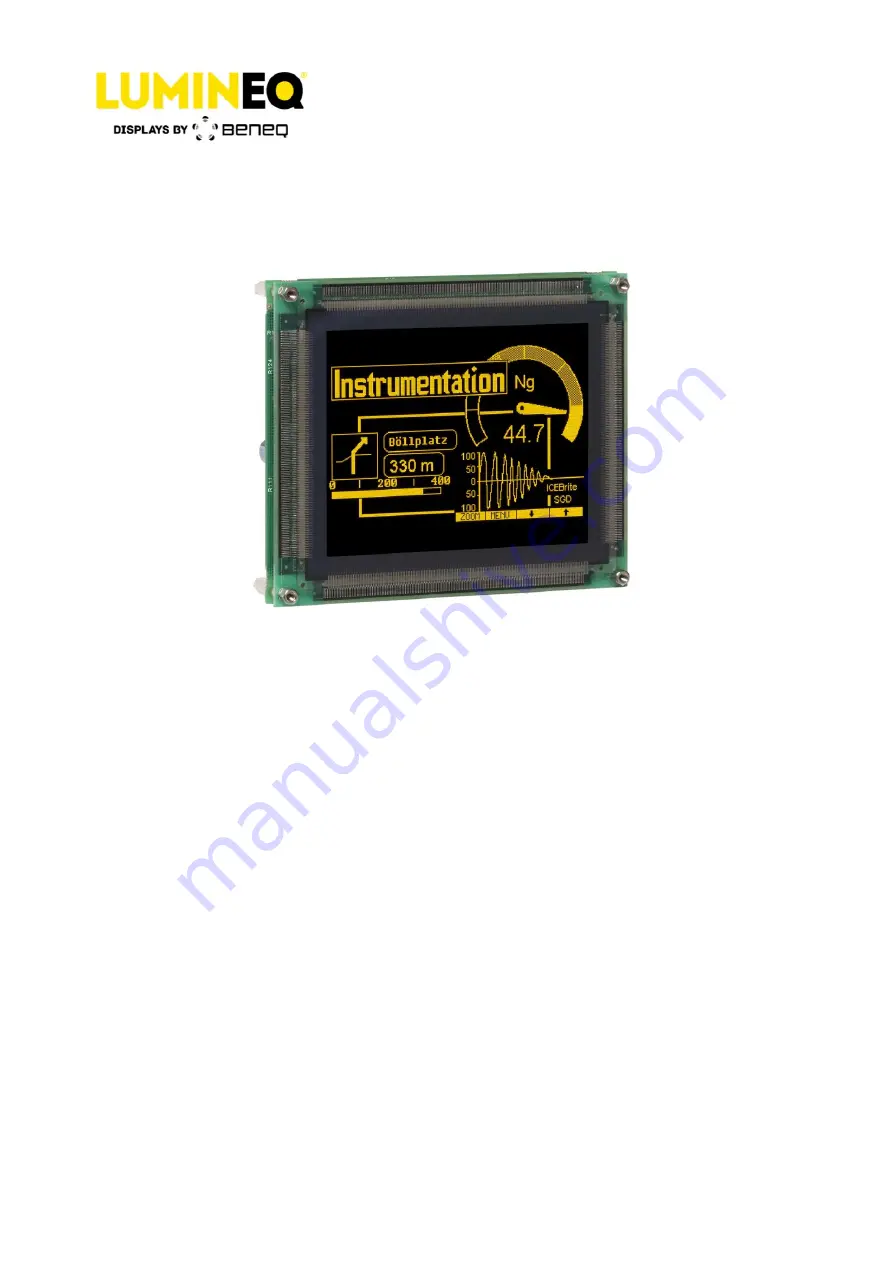
EL320.256-FD6 
Low Power TFEL Display 

Operation Manual 


Beneq Oy 


Olarinluoma 9


Tel. +358 9 7599 530


VAT ID FI19563372


FI-02200 Espoo


Fax +358 9 7599 5310


www.beneq.com


Finland


[email protected]


www.lumineq.com


Date: February 13, 2017


Document number: ED000814C


Page | 1 


EL320.256-FD6 

Operation Manual 


Summary of Contents for Lumineq EL320.256-FD6

Page 1: ...on Manual Beneq Oy Olarinluoma 9 Tel 358 9 7599 530 VAT ID FI19563372 FI 02200 Espoo Fax 358 9 7599 5310 www beneq com Finland lumineq beneq com www lumineq com Date February 13 2017 Document number ED000814C Page 1 EL320 256 FD6 Operation Manual ...

Page 2: ... jumpers 5 3 3 Connectors 6 3 4 Control basics 6 3 5 Power input 6 4 Display features 7 4 1 Low power mode 7 4 2 Two bits parallel 7 4 3 Brightness control 7 4 4 Self test 7 4 5 Input specifications 8 4 6 Timing characteristics 9 4 7 Setup and hold timing 10 5 Operational specifications 11 5 1 Environmental 11 5 2 Reliability 11 5 3 Safety 11 5 4 Electromagnetic compatibility 11 5 5 Optical 12 5 5...

Page 3: ...nterface is designed to match the needs of most systems The display may be driven at frame rates up to 75 Hz The EL320 256 FD6 display requires 5 V and 11 V to 30 V Vcc1 Vcc2 power and 4 basic signals to operate 1 Video Data or pixel information VID 2 Video Clock pixel clock or dot clock VCLK 3 Horizontal Sync HS 4 Vertical Sync VS 2 TFEL technology The display consists of an electroluminescent gl...

Page 4: ...uminance contrast of the display in bright ambient ICEBrite also removes the halo around the lit pixels in dark ambient making the appearance of each pixel crisp and clear In the EL320 256 FD6 display the 320 column electrodes and 256 row electrodes are arranged in an X Y formation with the intersecting areas performing as pixels Voltage is applied to both the correct row electrode and the correct...

Page 5: ...olumn data input for optional two bit parallel mode See page 6 9 Vertical Sync VS The vertical sync signal VS controls the vertical position of the picture The topmost row displayed is the first HS HIGH time ending after the rising edge of the VS 11 Horizontal Sync HS The horizontal sync signal HS controls the horizontal position of the picture The last 320 pixels before the fall of HS are display...

Page 6: ...LFTEST When set video data input in VID and TVID is displayed asynchronously 3 3 Connectors Table 2 Connectors J1 16 pin header ODU 511 066 003 016 or eq Mating ODU 517 065 003 016 or eq J2 4 pin header Hirose DF1 4P 2 5 DSA or eq Mating Hirose DF1 4S 2 5 R 24 or eq Protector Hirose DF1 4A 1 33 3 4 Control basics The TFEL panel has 320 transparent column electrodes crossing 256 row electrodes in a...

Page 7: ...it is possible to input the data of two pixels per pixel clock This feature is selected with the DCONFIG jumper PS1 2 If the jumper is set data for even columns is input in VID and data for odd columns is input in TVID If the jumper is open data is input normally to VID only 4 3 Brightness control The brightness of the display can be adjusted from below 10 up to full brightness by a 50 kΩ external...

Page 8: ...Vcc1 4 75 V 5 0 V 5 25 V 6 0 V abs max Supply current at 5 V Icc1 0 1 A 0 2 A Supply voltage Vcc2 10 8 V 30 V 33 V abs max Supply current at 12 V Icc2 0 3 A 0 6 A Supply current at 12 V Low Power Icc2 0 2 A 0 4 A Power consumption 4 W 8 2 W Power consumption Low Power 3 W 5 W Operating conditions Ambient temperature 25 C 60 Hz NOTE Absolute maximum ratings are those values beyond which damage to t...

Page 9: ...er ED000814C Page 9 4 6 Timing characteristics Figure 3 Timing characteristics Table 4 Timing characteristics Description Min Max Unit Note T1 Vertical Front Porch 100 µs 1 T2 VS HIGH LOW time 30 ns 2 T3 Vertical Blank 70 µs T4 Vertical Period 256 tHS VS frequency 75 Hz Description Min Typ Unit Note T5 HS setup to VS 1 µs 3 T6 HS hold from VS 3 µs T7 HS Low Time 4 tVCLK T8 HS High Time 320 320 tVC...

Page 10: ...he last row and to initiate the following frame 2 Only rising edge is used 3 2 tVCLK minimum 4 The number of VCLK pulses during HS high time must be even Video clock VCLK must be kept running continuously 4 7 Setup and hold timing Figure 4 Setup and hold timing Table 5 Setup and hold timing Symbol Description Min Max tSU HS VID TVID setup to VCLK 5 ns tHOLD HS VID TVID hold from VCLK 8 ns tWL VCLK...

Page 11: ...perating IEC 60068 2 78 Damp heat 25 C 55 C 95 RH non operating IEC 60068 2 30 Altitude 15 000 m 50 000 ft above sea level Standard IEC 60068 2 13 Vibration 20 500 Hz ASD level 0 05 g2 Hz 30 min each axis Standard IEC 60068 2 64 Random Vibration Test Fdb Shock Magnitude Duration Number of shocks 100 g 4 ms half sine wave 18 3 on each of the 6 surfaces IEC 60068 2 27 test Ea 5 2 Reliability MTBF 50...

Page 12: ...real luminance On Luminance typ 25 cd m2 7 3 fL On Luminance min 22 cd m2 6 4 fL Low power min 18 cd m2 5 2 fL Measured at the center and the four corners of the screen Luminance non uniformity 20 max Low Power 26 max 1 min luminance max luminance x 100 Maximum difference between any two of five points center and four corners Luminance variation time Maximum 10 15 000 h 25 C Luminance variation te...

Page 13: ...0 30 0 012 width 0 30 0 012 Pixel size millimeters inches height 0 30 0 012 width 0 30 0 012 Pixel fill factor 49 Pixel matrix 320 horizontal by 256 vertical CAUTION The ambient temperature of the display should not be allowed to exceed the environmental specifications see page 9 In most applications an air gap of a minimum of 5 mm is recommended see mechanical drawings Some applications may requi...

Page 14: ...uary 13 2017 Document number ED000814C Page 14 ELECTROSTATIC CAUTION The Beneq display uses CMOS and power MOS FET devices These components are electrostatic sensitive Unpack assemble and examine this assembly in a static controlled area only When shipping use packing materials designed for protection of electrostatic sensitive components Figure 5 EL320 256 FD6 display viewing area characteristics...

Page 15: ... touching the display necessary precaution must be taken to prevent application of static charges on the display from the operator or tools The display is made of glass material and should be handled with proper care Do not drop the display or allow hard objects to strike its surface NOTE For trouble free data transfer a maximum cable length of 300 mm 12 in from data transmitter to display input c...

Page 16: ...to properly store install operate handle or maintain the goods are not within this warranty Repair or replacement of goods is seller s sole obligation and buyer s exclusive remedy for all claims of defects If that remedy is adjudicated insufficient Seller shall refund buyer s paid price for the goods and have no other liability to buyer All warranty repairs must be performed at seller s authorized...

Page 17: ...S II or RoHS Recast which compared to RoHS keeps the restrictions on the original six hazardous substances including lead Pb in electronic equipment It also expands these restrictions to previously exempted categories including medical devices and monitoring and control instruments Beneq part number with an LF suffix designation indicates RoHS compliance as shown on the part number label affixed t...

Reviews: