Operating Manual
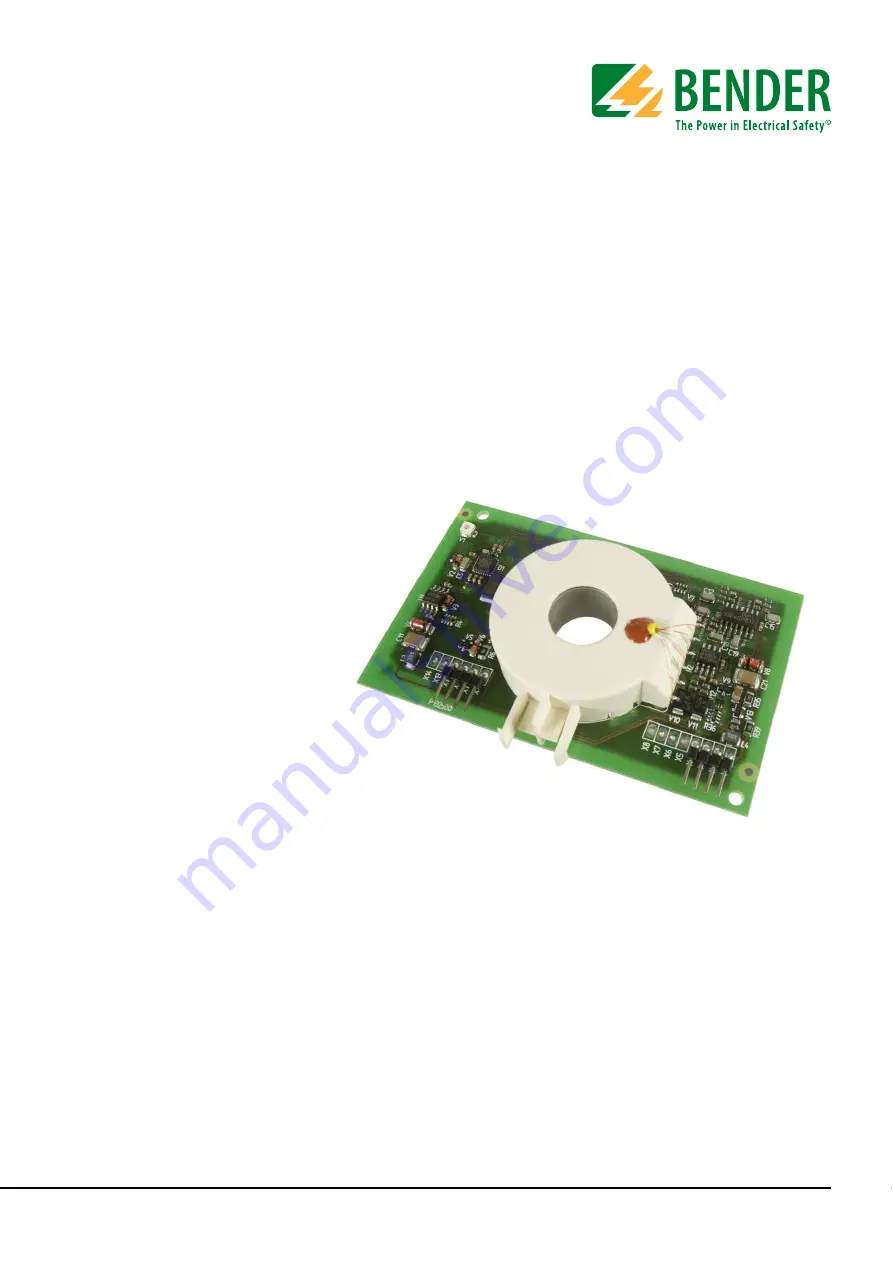
RCMB102
AC/DC sensitive
residual current monitoring module
for installation into electric vehicle charging stations
Software version D395 V1
TGH1475en/11.2012
Page 1: ...Operating Manual RCMB102 AC DC sensitive residual current monitoring module for installation into electric vehicle charging stations Software version D395 V1 TGH1475en 11 2012...
Page 2: ...ing only with permission of the publisher Subject to change Bender GmbH Co KG Londorfer Str 65 35305 Gr nberg Germany Postfach 1161 35301 Gr nberg Germany Tel 49 6401 807 0 Fax 49 6401 807 259 E mail...
Page 3: ...ction 7 2 3 Starting sequence 8 2 4 Analogue voltage output X1 10 2 5 Switching output X12 10 2 6 Control input X10 10 2 6 1 Cyclical self test 10 2 6 2 Reset function 11 2 6 3 Impulse duration for ac...
Page 4: ...7 3 3 Example applications 18 3 3 1 The circuit breaker is controlled by the charging control electronics and the switching output X12 18 3 3 2 The circuit breaker is controlled by the charging contro...
Page 5: ...identify important instructions and information The meaning of these symbols is explained below 1 3 Intended use The AC DC sensitive residual current monitoring module RCMB102 is used for monitoring...
Page 6: ...t accept any liability for injury to persons or damage to property resulting from errors or mistakes in this manual 1 5 Personnel Only appropriately qualified personnel may work on the Bender product...
Page 7: ...he residual current monitoring module detects the residual current caused by leakage and residual currents in the conductors passed through the measuring current transformer The residual current monit...
Page 8: ...e enables the switching output X12 LOW level Test current supply 5 The test winding is supplied with test current for 2 s two stage test current The resulting measured value is available at X1 and the...
Page 9: ...X12 HIGH Delay 0 05 0 1 ms X12 HIGH 10 11 ms X10 50 s HIGH No Yes No Yes Yes Yes No No X10 100 s HIGH Yes No No Yes Switch on test current through test winding Test current measurement Switch off tes...
Page 10: ...toring module the switching output X12 will be disabled and signalled by the open collector output X12 Fig 2 2 Open collector Only when the measured value of the residual current falls below 10 mA for...
Page 11: ...6 3 Impulse duration for activating a reset When a LOW level is applied at the control input X10 of the residual current monitoring module for T 530 ms no reset will be carried out The outputs X1 and...
Page 12: ...ibration T2 50 100 s X12 X1 T4 4 6 s T3 10 11 ms Begin of calibration process End of calibration process Start of residual current measurement HIGH LOW LOW HIGH t2 T5 0 1 s T6 0 15 s T7 0 85 s T9 5 ms...
Page 13: ...0 100 s is applied at the control input X10 Calibration starts within 10 11 ms T3 The RCMB disables the open collector switching output X12 HIGH and carries out an offset measurement The DC component...
Page 14: ...abled after 2 3 s If X10 is maintained at LOW level at the end of the self test X12 remains disabled until X10 has reached HIGH level for at least 5 ms Refer to the diagram in chapter 2 6 4 for more i...
Page 15: ...current see chapter 2 8 If the residual current monitoring module detects values outside the measuring range the analogue output X1 will be set to 4 85 V As soon as the residual current drops to 10 mA...
Page 16: ...nt transformer winding Frequency measurement of the measuring oscillator X1 5 0 V X12 HIGH Constant output voltage at the measuring oscillator Frequency measurement of the measuring oscillator X1 5 0...
Page 17: ...ing current transformer Plug designation Description X1 Analogue voltage output X2 US Voltage supply 12 V via current limiting or 100 mA fuse recommended X3 GND ground X4 not connected X9 GND ground X...
Page 18: ...ctronics The circuit breaker is controlled by the charging control electronics software The switching output X12 and the analogue output X1 are monitored by the charging system to ensure that the outp...
Page 19: ...V 10 mA Tolerance at 1 5 10 mA 0 20 1 mA Tolerance at 10 50 mA 0 20 Tolerance at 0 15 V 50 mV 0 mV Tolerance at 4 85 V 150 mV 50 mV Output resistance at the measurement outputX1 1 k short circuit proo...
Page 20: ...lassification of climatic conditions Ambient temperature during operation 25 C 80 C Ambient temperature during transport 40 C 80 C Ambient temperature during long time storage 25 C 80 C Relative humid...
Page 21: ...Technical data 21 TGH1475en 11 2012 4 3 Dimension diagrams Dimensions are given in mm...
Page 22: ...Technical data 22 TGH1475en 11 2012...
Page 23: ......
Page 24: ...Bender GmbH Co KG Londorfer Str 65 35305 Gr nberg Germany Postfach 1161 35301 Gr nberg Germany Tel 49 6401 807 0 Fax 49 6401 807 259 E Mail info bender de com Web http www bender de com...