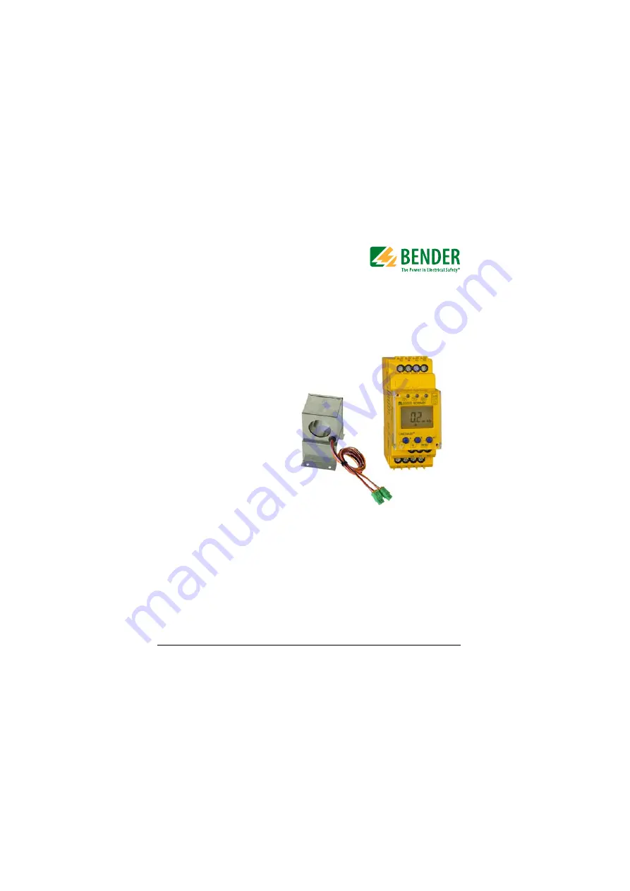
Manual
RCMA421H-DCB
WN-35BS
Residual current monitor
for monitoring AC, DC and pulsed DC currents
in earthed and resistance earthed systems
Software version D290 V1.0x
RCMA421H-DCB_D00062_00_M_XXEN/05.2014
Page 1: ...nual RCMA421H DCB WN 35BS Residual current monitor for monitoring AC DC and pulsed DC currents in earthed and resistance earthed systems Software version D290 V1 0x RCMA421H DCB_D00062_00_M_XXEN 05 20...
Page 2: ...rinting only with permission of the publisher Subject to change Bender GmbH Co KG P O Box 1161 35301 Gruenberg Germany Londorfer Str 65 35305 Gruenberg Germany Tel 49 6401 807 0 Fax 49 6401 807 259 E...
Page 3: ...rical installations 7 2 3 Device specific safety instructions 7 3 Function 9 3 1 Device features 9 3 2 Description of function 10 3 2 1 Transformer monitoring 10 3 2 2 Quick query of the rated residua...
Page 4: ...the fault memory 20 5 6 Calling up and exiting the menu 20 5 7 Making settings in the menu 21 5 7 1 Selecting menus 21 5 7 2 Querying the software version with the InF menu 22 5 7 3 Setting the bus ad...
Page 5: ...uring current transformer WN 35BS is used to monitor earthed and resistive earthed systems TN and TT systems in which DC and AC fault currents may occur These systems involve loads with six pulse bri...
Page 6: ...Making effective use of this document 6 RCMA421H DCB_D00062_00_M_XXEN 05 2014...
Page 7: ...iated with them is mandatory EN 50110 is of particular importance in this regard If the device is being used in a location outside the Federal Republic of Germany the applicable local standards and re...
Page 8: ...Safety instructions 8 RCMA421H DCB_D00062_00_M_XXEN 05 2014...
Page 9: ...sured value display via multi functional LCD Alarm signalling via LEDs TPD ERR and K2 changeover contact Password protection to prevent unauthorised changes being made to device settings Permanent fau...
Page 10: ...switched the residual current must fall to less than the rated residual operating current If it does not error code E 04 will appear on the display and the ERR alarm LED willflash This means that the...
Page 11: ...t without internal fault current The alarm relay is not switched during the 24 hour test 3 2 4 Self test manual The device runs a self test when the test button is pressed 1 5 s Any inter nal malfunct...
Page 12: ...ing entered 0 999 3 2 7 Factory setting FAC Activating the factory setting will reset all modified settings with the excep tion of the device address to the default upon delivery 3 2 8 Erasable histor...
Page 13: ...dimension diagram and drawing for screw fixing The front plate cover is easy to open at the lower part marked by an arrow Makesurethattheinstallationareahasbeen de energisedand ensure compliance with...
Page 14: ...Installation and connection 14 RCMA421H DCB_D00062_00_M_XXEN 05 2014 Dimension diagram for measuring current transformer WN 35BS Dimensions in mm 62 51 20 42 57 90 79 37 4 60 35 99 50 71...
Page 15: ...s 2 Wiring The device must be wired as illustrated in the connection diagram example Terminal Connections A1 A2 Connection to the power supply voltage Us 1 Bush for measuring current transformer s con...
Page 16: ...r and the associ ated contactors and peripherals have been connected correctly Colour Pin assignment Colour Pin assignment Brown k1 Black I1 Orange k2 Red I2 Pink T Violet T Rated residual operating c...
Page 17: ...lashes in the event of system errors An error code will appear on the display e g E 03 4 DISPLAY Displays operating information 5 ENTER 1 5 s MENU 1 5 s button Press this button to apply entries and c...
Page 18: ...ton restores the measured value 5 3 Getting to know buttons and button functions The table below lists the functions of the buttons when navigating through the display navigating through the menu and...
Page 19: ...ory item Activate parameter Change increase parameter value Press and hold down button for more than 1 5 seconds run manual self test Down Reset Call up next display Go to next menu sub menu Deactivat...
Page 20: ...has an erasable fault memory To erase the fault memory Press and hold down the reset button R DOWN for more than 1 5 sec onds 5 6 Calling up and exiting the menu To call up the menu Press and hold do...
Page 21: ...the ENTER button for less than 1 5 s to call up a menu Press and hold down the ENTER button for more than 1 5 seconds to go to the next highest menu Menu Button to call Description Configurable parame...
Page 22: ...P DOWN buttons to se lect individual items 5 7 3 Setting the bus address 1 Select the Adr menu 2 Make changes to parameters as illustrated 3 To go back to the menu level press and hold down the ENTER...
Page 23: ...device can be reset to the factory settings 1 Select the SEt menu 2 Make changes to parameters as illustrated To go back to the menu level press and hold down the ENTER button for more than 1 5 secon...
Page 24: ...e password protection 4 Switch sub menu 5 Restore factory setting run appears on the display and the device is reset to the factory settings automatically 6 Switch sub menu SEt menu Select sub menu Ch...
Page 25: ...3 To go back to the menu level press and hold down the ENTER button for more than 1 5 seconds 7 System menu is locked 8 Switch sub menu 9 Go back to SEt menu HIS menu Error display Sub menu 1 Error Ra...
Page 26: ...Operation and configuration 26 RCMA421H DCB_D00062_00_M_XXEN 05 2014 4 Switch error display 5 Erase fault memory 6 Switch error display 7 Go back to HIS menu HIS menu Error display Sub menu...
Page 27: ...voltage Supply voltage range Us AC DC100 250V Operatingrange Us AC DC 70 300 V Frequency range Us 42 460 Hz Power consumption 6 5 VA Measuring circuit External measuring current transformer WN 35BS Ra...
Page 28: ...e shielded shield connected to PE at one end At least J Y St Y 2 x 0 6 Terminating resistor can be switched 120 0 25 W off Bus address 2 90 2 Switching elements Number of switching elements 1 changeov...
Page 29: ...nection For UL application use 60 70 C copper conductors only Connection type screw terminals Rigid flexible conductor sizes 0 2 4 0 2 2 5 mm2 AWG 24 12 Multi conductorconnection 2 conductors with the...
Page 30: ...ip Software version D290V1 0 Weight RCMA421H 150 g Weight WN 35BS 355 g factory setting 6 2 Error codes If contrary to expectations a device error should occur error codes will ap pear on the display...
Page 31: ...e error has been eliminated E 03 Connection error short circuit transformer Action Check transformer connection for short circuit or open circuit from k1 to I1 E 04 Error K1 Q1 following powering up t...
Page 32: ...3 1 A26 30 10 84 3 1 A40 30 10 84 3 1 A75 30 00 84 3 A110 30 00 84 3 A145 30 00 84 3 A16 30 10 34 3 1 A26 30 10 34 3 1 A40 30 10 34 3 1 A75 30 00 34 3 A110 30 00 34 3 A145 30 00 34 3 A16 40 00 84 4 A2...
Page 33: ...D00062_00_M_XXEN 05 2014 6 4 Response times of the RCMA421H system plus contac tor in accordance with UL943 30 0 560 6 5 594 264 0 0250 0 01 0 10 1 00 10 00 0 20 40 60 80 100 120 140 160 180 200 220 2...
Page 34: ...r and test combination 6 6 Standards approvals and certifications RCMA421H DCB 2 Rated residual operating current I n 6 mA Rated frequency 0 150 Hz Supply voltage Us AC DC 70 300 V AC 42 460 Hz Art No...
Page 35: ...function 10 Device features 9 Dimension diagram 13 E Error codes 30 F Factory setting 12 16 Fault memory 25 H HIS menu 25 I Installation and connection 13 Instructions for use 5 M Malfunction 12 Manua...
Page 36: ...M_XXEN 05 2014 Response delay t 12 RS 485 interface 15 S Self test automatic 11 Self test manual 11 20 SEt menu 23 Standards approvals and certifications 34 T Technical data 27 W Wiring 15 Working on...
Page 37: ...37 RCMA421H DCB_D00062_00_M_XXEN 05 2014...
Page 38: ...38 RCMA421H DCB_D00062_00_M_XXEN 05 2014...
Page 39: ......
Page 40: ...Bender GmbH Co KG P O Box 1161 35301 Gruenberg Germany Londorfer Str 65 35305 Gruenberg Germany Tel 49 6401 807 0 Fax 49 6401 807 259 E Mail info bender de Web http www bender de...