


Device communication
Device communication
isoPV1685xxx_D00007_05_M_XXEN/02.2020
23
Wiring
The following type of wiring is recommended for the RS-485 network:
J-Y(St)Y 2x0.8mm², shield connected to earth (PE) on one end.
Connection to terminals A and B.
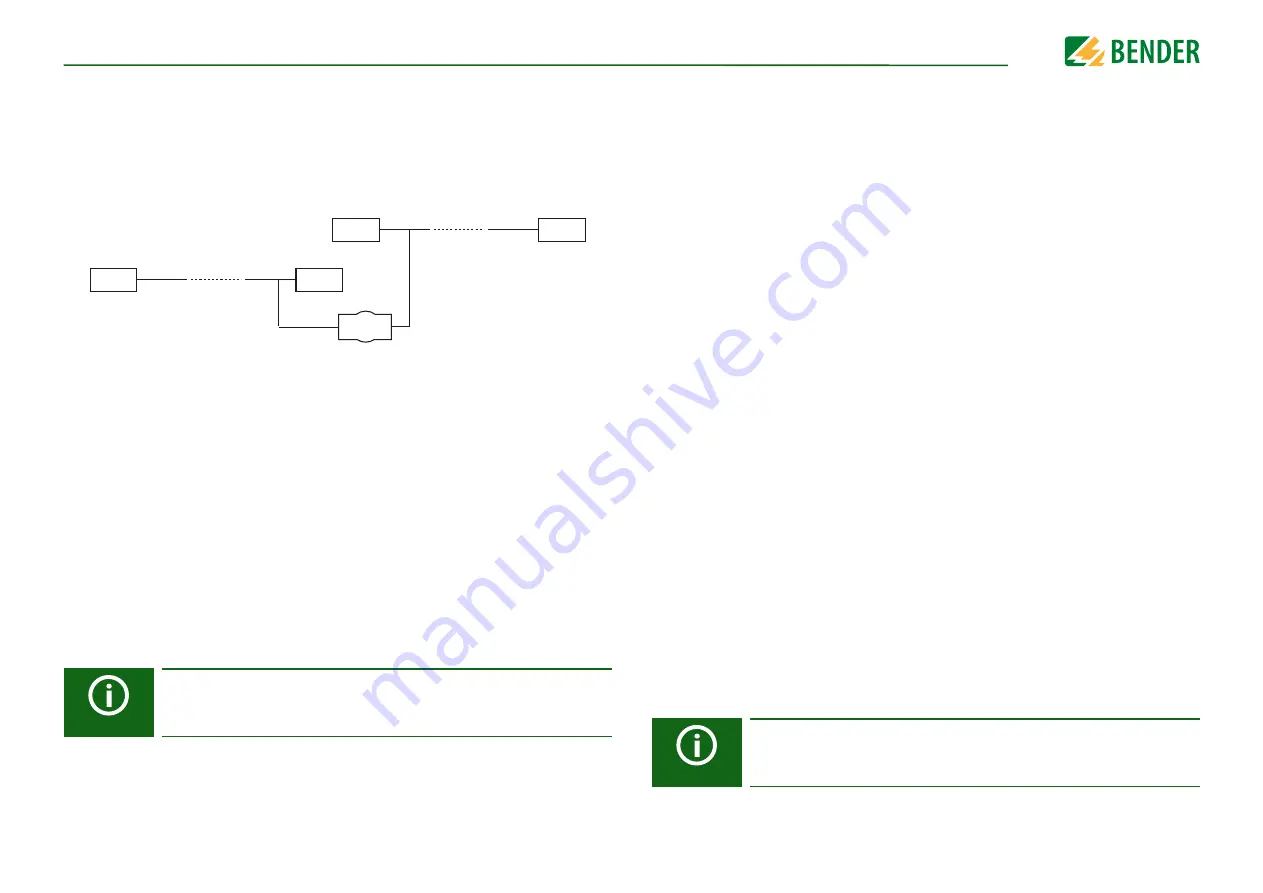
The maximum number of bus nodes is restricted to 32 devices. If more devices are to be
connected, Bender recommends the use of a DI1 repeater.
8.2 BMS bus
8.2.1 BMS protocol
This protocol is an essential part of the Bender measuring device interface (BMS bus pro-
tocol). Data transmission generally makes use of ASCII characters.
Interface data are:
•
Baud rate:9600 baud
•
Transmission:1 start bit, 7 data bits, 1 parity bit, 1 stop bit (1, 7, E, 1)
•
Parity:even
•
Checksum:Sum of all transmitted bytes = 0 (without CR and LF)
The BMS bus protocol works according to the MASTER-SLAVE principle. Only one MAS-
TER may exist in each network. All bus devices are identified by a unique BMS address.
The MASTER cyclically scans all other slaves on the bus, listens to their signals and then
carries out the corresponding commands.
A device receives the MASTER function by assigning
bus address 1
to it.
The isoPV1685... can only be operated as BMS SLAVE!
DI1
1
32
33
64
BMS master
A master can query all measured values, alarm and operating messages from a slave.
If bus address 1 is assigned to a device, this device automatically represents the master,
i.e. all addresses between 1 and 150 are cyclically scanned via the BMS bus for alarm and
operating messages. If the master receives no answer from five subsequent addresses,
the scanning cycle will start again. If the master detects incorrect answers from a slave,
the fault message "Fault RS-485" will be output via the BMS bus.
Fault causes may be:
•
Addresses are assigned twice
•
A second master exists on the BMS bus
•
Interference signals occur on the bus lines
•
A defective device is connected to the bus
•
Terminating resistors are not activated or not connected
The ISOMETER® isoPV1685P cannot be a master and cannot have address 1. However, if
there is no master in the system, the ISOMETER® isoPV1685P becomes the backup master
with a different BMS address (e.g. 2 or 3). Communication with the slaves in the system
can be carried out via the backup master.
8.2.2 Commissioning of an RS-485 network with BMS protocol
•
Interconnect terminals A and B of all bus devices in one line
•
Switch the terminating resistors on at the start and the end of the RS-485 network. If
a device at the end of the bus is not terminated, connect a 120 Ω resistor to termi-
nals A and B
•
Switch the supply voltage on
•
Assign the master function and address 1 to a bus-capable device
•
Assign addresses to all other bus devices in consecutive order
–
isoPV1685RTU: Address range 2…17
–
isoPV1685P: Address range 2…33
8.2.3 Setting the BMS address
The factory setting of the BMS address can be changed using the DIP switch SS8103. Fac-
tory setting BMS address = 2.
isoPV1685RTU:
The A4 switch of the dip switch SS8103 is used to switch between BMS and
Modbus
(refer to