


Settings
Settings
iso685-D-B_D00177_05_M_XXEN/07.2017
37
Select the appropriate setting for function 1. The following parameters can be set.
•off
The function is not used.
•Ins. Alarm 1
The status of the output changes when the value falls below the set
response value R
an1.
•Ins. Alarm 2
The status of the output changes when the value falls below the set
response value R
an2.
•Connection fault
The status of the output changes when one of the following connec-
tion fault occurs:
• No low-resistance connection between the line conductors.
• No low-resistance connection between the terminals E and KE to
earth (PE).
• The load connected to the current output is too low
• The load connected to the current output is too high.
• Load on X1 too high.
•DC alarm
The status of the output changes in case of an earth fault in the
direction of DC when 75 % of the value are exceeded. This does not
concern symmetrical faults. This function will only be carried out
when the value falls below the response value
R
an1
or
R
an2
and
when the nominal system voltage is
U
n
≥ 50 V.
•DC+ alarm
The status of the output changes in case of an earth fault in the
direction of DC+ when 25 % of the value are exceeded. This does not
concern symmetrical faults. This function will only be carried out
when the value falls below the response value
R
an1
or
R
an2
and
when the nominal system voltage is
U
n
≥ 50 V.
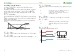
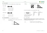
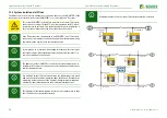
•Symmetrical
alarm
The status of the output changes in the event of a resistance ratio
between DC+ and DC- of 25 % to 75 %.
DC+ alarm
Symmetrical alarm
DC- alarm
0 %
25 %
50 %
75 %
100 %
10.1
(1.10.1.4) Function 2
Refer to
10.1
(1.10.1.5) Function 3
Refer to
10.1
(1.10.2) Relay 2
Refer to
10.1
(1.10.3) Digital 1
The following parameters can be set for each of the digital outputs:
•Device fault
The status of the output changes in the event of an internal device
fault.
•Common alarm
The status of the output changes on the occurrence of any alarm
and fault messages
(Ins. alarm 1 & 2, DC- / DC+ alarm, symmetrical alarm, connection
and device faults).
•Measurement
complete
The status of the output changes at the end of the initial
measurement.
•Device inactive
The status of the output changes when the device has been
deactivated via a digital input or the control menu.
•DC offset alarm
The status of the output changes on the occurrence of a DC offset
voltage in the system.


