


45
iso1685FR(M)_D00002_02_M_XXEN/06.2017
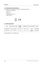
10. Technical data
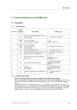
10.1 Tabular data
Insulation coordination acc. to IEC 60664-1 / IEC 60664-3
Insulation coordination according to IEC 60664-1
Rated insulation voltage (terminals L1/L2 to E/KE) .............................................................................................................................................................................. 5 kV
Overvoltage category .................................................................................................................................................................................................................................... II
Pollution degree ........................................................................................................................................................................................................................................... 2
Voltage ranges
Nominal system voltage
U
n
L1+/L2-................................................................................................................................................................................. AC 0…400 V**
Phase-to-phase voltage .............................................................................................................................................................................................................AC 0…5 kV
Voltage component L1/+ to PE (U
N-PE
) ........................................................................................................................................................................... AC 0…3 kV***
Voltage component L2/- to PE (U
L1‘-PE
) ............................................................................................................................................................................ AC 0…3 kV***
Supply voltage
U
S
(Also refer to the device name plate) ...................................................................................................................................................... DC 18…30 V
Power consumption ............................................................................................................................................................................................................................. ≤ 7 W
Power consumption .......................................................................................................................................................................................................................... ≤ 7 VA
Measuring circuit for insulation monitoring
Measuring voltage
U
m
(effective value) ................................................................................................................................................................................................. 34 V
Measuring current
I
m
(when
R
e
= 0 Ω) ........................................................................................................................................................................................ ≤ 150 μA
Internal DC resistance
R
i
................................................................................................................................................................................................................. ≥ 260 kΩ
Impedance
Z
i
at 50 Hz.................................................................................................................................................................................................................... ≥ 260 kΩ
Permissible extraneous DC voltage
U
fg
.................................................................................................................................................................................................... 0 V
Permissible system leakage capacitance
C
e
................................................................................................................................................................................... ≤ 200 nF
Response values for insulation monitoring (active method)
Response value
Z
an
(Alarm) ................................................................................................................................................................................... 10…1000 kΩ (25 kΩ)*
Relative uncertainty (100 kΩ…1 MΩ) (acc. to IEC 61557-8:2007-01) ........................................................................................................................................... ±15 %
Relative uncertainty (10…100 kΩ).................................................................................................................................................................................... ± 5 kΩ
± 15 %
Response time
t
an
(for measurement buffer size MPT = 3) ........................................................................................................................................................ ≤ 150 ms
Hysteresis................................................................................................................................................................................................................................................ 25 %
Response values for insulation monitoring (passive method)
Response value
U
an
(Alarm) ....................................................................................................................................................................................... 0…3000 V (125 V)*
Relative uncertainty (100…3000 V)................................................................................................................................................................................................. ± 5 %
Relative uncertainty (1…100 V.............................................................................................................................................................................................. ± 5 V
± 5 %
Response time
t
an
(for measurement buffer size MPT = 3) ........................................................................................................................................................ ≤ 150 ms
Hysteresis................................................................................................................................................................................................................................................ 25 %
Displays, memory
LEDs for alarms and operating states ........................................................................................................................................................................... 1 x green, 3 x yellow
μSD card for history memory and log files ...................................................................................................................................................................................... ≤ 32 GB
Digital inputs
I1+, I1- (high active) ....................................................................................................................................................................................................................no function
I2+, I2- .........................................................................................................................................................................................................................................no function
Analog output (via ICP M-7024 Modbus analog converter):
Number.......................................................................................................................................................................................................................................................... 1
Operating principle............................................................................................................................................................................. linear, 0…200 kΩ (refer to diagram)
Function .............................................................................................................................................................................................................................insulation value Z
e
Current ....................................................................................................................................................................................................................... 4…20 mA (< 600 Ω)
Tolerance ............................................................................................................................................................................................................................................. ±10 %
Summary of Contents for ISOMETER iso1685FR
Page 6: ...6 ...
Page 10: ...Important information 10 iso1685FR M _D00002_02_M_XXEN 06 2017 ...
Page 14: ...Safety instructions 14 iso1685FR M _D00002_02_M_XXEN 06 2017 ...
Page 42: ...Diagram for the calculation of Ze 42 iso1685FR M _D00002_02_M_XXEN 06 2017 ...
Page 44: ...Information about the measuring method 44 iso1685FR M _D00002_02_M_XXEN 06 2017 ...
Page 50: ...INDEX 50 iso1685FR M _D00002_02_M_XXEN 06 2017 ...
Page 51: ...INDEX 51 iso1685FR M _D00002_02_M_XXEN 06 2017 ...


