


Device communication
36
iso1685FR(M)_D00002_02_M_XXEN/06.2017
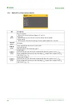
6.1.8 Resetting error messages
Recorded errors are provided as alarm messages on the BMS bus.
Pressing the reset button ST6101 will reset these error messages. If the fault continues to exist, the message will
be generated again.The error can also be reset by means of the acknowledgement command via the BMS bus.
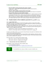
6.1.9 Starting the firmware update via the BMS bus
The firmware can be updated via the BMS bus using the BMS Update Manager which can be obtained from
Bender.
can be obtained from Bender.
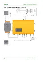
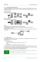
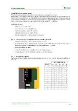
6.2 Device communication with Modbus RTU
The ISOMETER® iso1685FRM provides an analogue output by means of the Modbus-analogue converter.Com-
munication takes place via Modbus RTU.
The Modbus RTU protocol can only be used for communication between the ISOMETER® and the Modbus ana-
log converter.The Modbus RTU protocol is not available for further functions.
•
The Modbus RTU protocol is activated with the ISOMETER® DIP switch
(see
"chapter ISOMETER®s iso1685FRM DIP switch assignment"
•
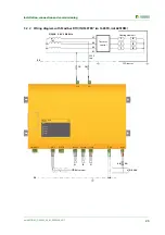
The wiring/connection diagram for the ISOMETER® iso1685FRM and Modbus analog converter can be
found under
"chapter 5.2.3 Anschlussplan mit Modbus RTU (ISOMETER® iso1685FRM)"
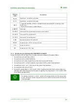
is also described in chapter
"chapter 5.2.5 Step-by-step connection of the iso1685FRM ISOMETER®"
.
•
For further information regarding commissioning, refer to
"chapter 5.3.2 Commissioning of the ISOMETER® iso1685FRM"
•
Both the data sheet and manual of the Modbus analog converter M7024 contain further information
about the device and the Modbus protocol.You can find these documents on our homepage at
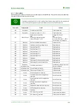
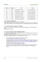
9.83
System
ADC channel U
E-KE
overload
Check system/connection
9.84
System
ADC channel U1
supply1
overload
Check system/connection
9.85
System
ADC channel U
Temp
overload
Check system/connection
9.86
System
ADC channel U
posPE
overload
Check system/connection
9.87
System
ADC channel U
MVS
overload
Check system/connection
9.88
System
ADC channel U
PCP
overload
Check system/connection
9.89
System
ADC channel U1
supply2
overload
Check system/connection
9.90
System
ADC channel U
negPE
overload
Check system/connection
Error code
Components
Fault
Action
Summary of Contents for ISOMETER iso1685FR
Page 6: ...6 ...
Page 10: ...Important information 10 iso1685FR M _D00002_02_M_XXEN 06 2017 ...
Page 14: ...Safety instructions 14 iso1685FR M _D00002_02_M_XXEN 06 2017 ...
Page 42: ...Diagram for the calculation of Ze 42 iso1685FR M _D00002_02_M_XXEN 06 2017 ...
Page 44: ...Information about the measuring method 44 iso1685FR M _D00002_02_M_XXEN 06 2017 ...
Page 50: ...INDEX 50 iso1685FR M _D00002_02_M_XXEN 06 2017 ...
Page 51: ...INDEX 51 iso1685FR M _D00002_02_M_XXEN 06 2017 ...


