


Function
17
iso1685FR(M)_D00002_02_M_XXEN/06.2017
is triggered. This function can be used to prevent the active process from being continuously interrupted,
which in turn means that insulation errors could then be found.
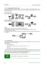
3.3.1.2 Passive method
Parallel to the active measuring method, a passive method is integrated for single-phase faults on the respec-
tive live conductors (phases), which monitors the voltage between the neutral point of the IT network and
earth.
If the voltage
U
N-PE
between the neutral point and earth exceeds the set response value
U
an
, the Alarm LEDs
ALARM 1 and ALARM 2 light up and the Alarm relays K1 and K2 are switched.
Both measuring methods (active and passive) work in parallel to the alarm relays K1 und K2 as well as the Alarm
LEDs ALARM 1 and ALARM 2. Redundant changerover contacts are therefore available for the notification of
insulation faults.
3.3.2 Connection monitoring
The following tests are continuously carried out in the background:
•
Connection E-KE
•
Connection to the system (L1/+, L2/–)
3.3.3 Assignment of the alarm relays K1, K2, K3
•
Alarm relay K1 switches when the value falls below the response value Z
an
(insulation impedance).
•
Alarm relay K2 switches when the value falls below the response value Z
an
(insulation impedance).
•
Alarm relay K3 switches in the event of a device error or a connection fault.
If the passive method is enabled, then the relays also switch.
•
Alarm relay K1 switches when the voltage
U
N-PE
exceeds the set response value
U
an
.
•
Alarm relay K2 switches when the voltage
U
N-PE
exceeds the set response value
U
an
.
•
Alarm relay K3 switches in the event of a device error or a connection fault.
3.3.4 Measured value transmission
All recorded measured values, operating messages and alarms are made available via the BMS bus.
3.4 History memory
All warnings, alarms and device errors are stored in the internal history memory with date and time stamp. The
time the event started, the time of acknowledgement and the end of the event are recorded.
The history data are copied from the internal EEPROM to the History.csv file on the μSD card under the fol-
lowing conditions:
– Follo
– a compatible μSD card has been inserted
– For the evaluation of the history memory, the Excel tool "iso1685 History.xlsx" can be made
available.
Summary of Contents for ISOMETER iso1685FR
Page 6: ...6 ...
Page 10: ...Important information 10 iso1685FR M _D00002_02_M_XXEN 06 2017 ...
Page 14: ...Safety instructions 14 iso1685FR M _D00002_02_M_XXEN 06 2017 ...
Page 42: ...Diagram for the calculation of Ze 42 iso1685FR M _D00002_02_M_XXEN 06 2017 ...
Page 44: ...Information about the measuring method 44 iso1685FR M _D00002_02_M_XXEN 06 2017 ...
Page 50: ...INDEX 50 iso1685FR M _D00002_02_M_XXEN 06 2017 ...
Page 51: ...INDEX 51 iso1685FR M _D00002_02_M_XXEN 06 2017 ...


