


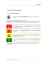


Safety instructions
12
iso1685FR(M)_D00002_02_M_XXEN/06.2017
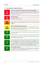
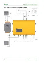
2.3 Device specific safety information
Danger as a result of excessive locating current or excessive locating voltage!
An excessive locating current of the internal locating current injector may damage sensitive
loads (e.g. control circuits) or trigger unwanted switching operations. Select a low locating
current for these systems. In case of doubt, please contact our service department (refer to
"chapter 1.2 Technical support"
).
Risk of electric shock!
When opening the device, you may come into contact with live parts. Switch off the mains
voltage before opening the device!
Make sure that the basic settings meet the requirements of the IT system. Persons without the
required expertise, in particular children, must not have access to or contact with the
ISOMETER®.
Make sure that the operating voltage is correct!
Prior to insulation and voltage tests, the ISOMETER® must be disconnected from the IT system
for the duration of the test. In order to check the correct connection of the device, a functional
test has to be carried out before starting the system.
In the event of an alarm message of the ISOMETER®, the insulation fault should be eliminated
as quickly as possible.
If the ISOMETER® is installed inside a control cabinet, the insulation fault message must be au-
dible and/or visible to attract attention.
When using ISOMETER®s in IT systems, make sure that only one active ISO-METER® is connec-
ted in each interconnected system. If IT systems are interconnected via coupling switches, ma-
ke sure that ISOMETER®s not currently used are disconnected from the IT system and
deactivated. IT systems coupled via diodes or capacitances may also influence the insulation
monitoring process so that a central control of the different ISOMETER®s is required.
Prevent measurement errors!
When a monitored IT system contains galvanically coupled DC circuits, an insulation fault
can only be detected correctly if the rectifier valves (e.g. rectifier diode, thyristors, IGBTs, fre-
quency inverters, …) carry a minimum current of > 10mA.
DANGER
DANGER
WARNING
CAUTION
Summary of Contents for ISOMETER iso1685FR
Page 6: ...6 ...
Page 10: ...Important information 10 iso1685FR M _D00002_02_M_XXEN 06 2017 ...
Page 14: ...Safety instructions 14 iso1685FR M _D00002_02_M_XXEN 06 2017 ...
Page 42: ...Diagram for the calculation of Ze 42 iso1685FR M _D00002_02_M_XXEN 06 2017 ...
Page 44: ...Information about the measuring method 44 iso1685FR M _D00002_02_M_XXEN 06 2017 ...
Page 50: ...INDEX 50 iso1685FR M _D00002_02_M_XXEN 06 2017 ...
Page 51: ...INDEX 51 iso1685FR M _D00002_02_M_XXEN 06 2017 ...


