


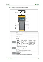


Operation
43
EDS309x_D00012_03_M_XXEN/11.2014
3. Connect the PGH18… to a suitable power supply using the power cable supplied (see name-
plate).
4. If there is an insulation monitoring device with an Ohmic internal resistance < 120 k
Ω
in the IT
system to be checked, disconnect it from the system to be checked on all poles. It is not suffi-
cient to switch off the power supply to the insulation monitoring device.
5. Set the maximum locating current using the I
max
switch on the PGH18…. Follow the instruc-
tions in chapter “Reduced locating current” on page 22.
6. Switch on the PGH18…. The "ON" LED illuminates and the two "
" and
"
" LEDs flash
alternately in synchronism with the
test cycle. If there is no activity indicated on the LEDs, check
the supply voltage and the fine-wire fuse that can be accessed from the front panel.
7. Switch on the EDS195P without a current transformer connected by pressing the
button.
The device undertakes a self-test and outputs the error message "No CT connected" because a
current transformer is not connected.
8. Now select the type of measuring clamp or measuring current transformer to be connected
using the
button. The device undertakes a further self-test and outputs the error message
"No CT connected" because a current transformer is not connected
9. Then connect the pre-selected measuring clamp or the pre-selected measuring current trans-
former to the EDS195P. The device undertakes a further self-test and is then in the EDS mode.
"
I
Δ
L
" appears in the first line of the display.
10. On
handling the measuring clamp
note:
– Do not bring measuring clamp into contact with system voltages above the rated insulation
voltage (see nameplate on the measuring clamp with information on measuring category,
e.g. CAT III)
– Always keep contact surfaces on measuring clamp's iron core clean.
– Do not use measuring clamp in the immediate vicinity of devices that produce magnetic
fields such as transformers or chokes and also not near adjacent conductors carrying high
currents.
– Never disconnect measuring clamp from the EDS195P while it is placed around electrically
live conductors. Otherwise the measuring clamp may be irreparably damaged!
– Aim for the best possible symmetry of the conductors in the measuring clamp. Otherwise
the measuring clamp may go into saturation due to an excessively high load current and
cause an alarm
I
Δ
n
>10 A.
–
Keep the measuring clamp still
during the measurement!
– During the measurement do not apply any pressure to the clamp limb.
11. Cover the green and yellow lead between PHG18… and earth with the measuring clamp. A
measurement process should take no more than 30 seconds. When the EDS195P is ready to
take a measurement, the countdown (29…0) at the top right corner of the display starts. If the
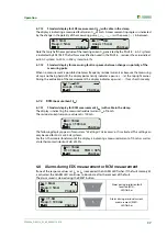
time has expired and no error has been found, the countdown starts again. During a measure-
ment, the EDS195P shows recognized test current signals with pauses in between:
i.e.
- - -
.
In the case of a measurement fault, the display permanently indicates pause (- - -).
There are 3 reasons for this:
– The insulation fault resistance is too high and cannot be measured by the EDS195P.
– The measuring clamp is not being held still. Hold the clamp still during measurement.
– Low frequency residual currents or magnetic fields in the environment have been superim-
posed on the test current pulse. Avoid these disturbances.
Summary of Contents for EDS3090
Page 6: ...Table of Contents 6 EDS309x_D00012_03_M_XXEN 11 2014...
Page 26: ...Considerations prior to use 26 EDS309x_D00012_03_M_XXEN 11 2014...
Page 62: ...Frequently Asked Questions 62 EDS309x_D00012_03_M_XXEN 11 2014...
Page 65: ......
Page 66: ......
Page 67: ......


