


Operation
42
EDS309x_D00012_03_M_XXEN/11.2014
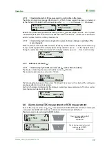
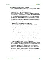
6.11.6 Menu item: I
Δ
n
logger
Using this menu item you can check the measured values recorded automatically during a residual
current measurement. The data records are numbered and contain the following information:
The start time for the measurement and the change in the residual current monitored
The residual current
I
Δ
n
measured
A maximum of 300 data records are saved.
The existing data records can be deleted using the menu.
6.12 Practical usage
6.12.1 Insulation fault location in a system without a permanently installed EDS system
The EDS309… is primarily used as a portable insulation fault location system in unearthed IT sys-
tems. Once all the instructions in chapter “Considerations prior to use” on page 19 have been fol-
lowed, insulation fault location can be started. Proceed as follows during this process:
1. Check whether the system voltage is within the permissible limits.
The permissible voltages are stated in the user interface on the PGH18….
2. Connect the locating current injector PGH18… close to the feed, see connection diagram on
page 28. During this process follow the general guidelines for working with electrically live sys-
tems!
– First connect the PE socket on the PGH18… to the system's PE using the green-yellow wire.
– Then connect the PGH18… to the system to be checked using the connection wires pro-
vided.
Level 1
Level 2
Level 3
Meaning
6. I
Δ
n logger
1. Exit
2. Entries
Entry No. 001
No. 002
No. ......
Time of the recording and
residual current I
Δ
n
measured
3. Change:
10…100 %
Percentage change from which log-
ging becomes active
4. Overwrite:
yes/no
Overwrite oldest data record
5. Delete
1. Exit
2. Data delete
Risk of electric shock!
On touching live uninsulated conductors, death or serious injury may be caused.
For this reason avoid any contact whatsoever with active conductors on con-
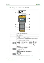
necting the PGH and positioning the measuring clamp.
Three-phase system
Connect sockets L1, L2 and L3 to the system
Single-phase AC or DC
Connect sockets L1 and L2 to the system
DANGER
Summary of Contents for EDS3090
Page 6: ...Table of Contents 6 EDS309x_D00012_03_M_XXEN 11 2014...
Page 26: ...Considerations prior to use 26 EDS309x_D00012_03_M_XXEN 11 2014...
Page 62: ...Frequently Asked Questions 62 EDS309x_D00012_03_M_XXEN 11 2014...
Page 65: ......
Page 66: ......
Page 67: ......


