


Considerations prior to use
20
EDS309x_D00012_03_M_XXEN/11.2014
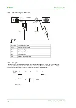
4.2 Requirements for reliable insulation fault location
The insulation fault locator has the task of locating the insulation fault
R
F-N
downstream
of the meas-
uring clamp. For this purpose, it must reliably detect the locating current caused by the insulation
fault.
Requirements:
The insulation fault must be present for at least 30s
The locating current is in the following ranges:
– Main circuits with EDS3090, EDS3090PG, EDS3090PG-13, EDS3092PG,
EDS3096PG-13, EDS3096PV, EDS3096PG:
I
L
= 2…50 mA
– Control circuits with EDS3091, EDS3091PG, EDS3091PG-13, EDS3092PG::
I
L
= 0.2…5 mA
The upstream capacitances
C
E-V
must be at least as large as the downstream capacitances
C
E-N
.
See also chapter "3.3.4 "
The total system leakage capacitance must not exceed the maximum values in the characteris-
tics in chapter "4.4 ".
The sum of the locating current and residual current flowing through the measuring clamp or
the measuring current transformer must not exceed the following values:
– Main circuits with EDS3090, EDS3090PG, EDS3090PG-13, EDS3092PG,
EDS3096PG-13, EDS3096PV, EDS3096PG:
maximum 10 A
– Control circuits with EDS3091, EDS3091PG, EDS3091PG-13, EDS3092PG:
maximum 1 A
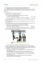
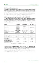
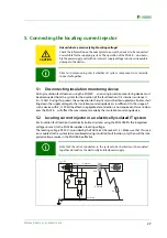
There must be no connections to other outgoing circuits
downstream of
a measuring clamp or
measuring current transformer, see sketch.
Abb. 4.2: Connections between outgoing circuits will result in measuring errors
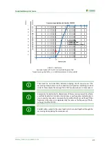
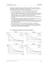
As well as the magnitude of the residual current, the frequency of the residual current also
affects the reliable detection of the locating current. Residual currents at frequencies other than
the system frequency may, e.g., be caused by the usage of frequency converters. The behaviour
of the EDS309… is described by the fault curve shown below:
– If the residual currents measured in
main circuits
exceed 10 A, the EDS195P outputs the
alarm message "
I
Δ
n
>10 A".
This statement applies to the system frequencies 50/60/400 Hz for the EDS3090,
EDS3090PG, EDS3090PG-13, EDS3092PG, EDS3096PG-13, EDS3096PV and EDS3096PG.
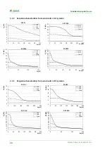
– If the residual currents measured in
control circuits
exceed 1 A, the EDS195P outputs the
alarm message "
I
Δ
n
>1 A".
This statement applies to the system frequencies 50/60/400 Hz for the EDS3091,
EDS3091PG, EDS3091PG-13 and EDS3092PG.
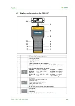
EDS195P
ISOSCAN®
I
L
I
n
ALARM
I n
I L
INFO
MENU
HOLD
RESET
ESC
OK
Summary of Contents for EDS3090
Page 6: ...Table of Contents 6 EDS309x_D00012_03_M_XXEN 11 2014...
Page 26: ...Considerations prior to use 26 EDS309x_D00012_03_M_XXEN 11 2014...
Page 62: ...Frequently Asked Questions 62 EDS309x_D00012_03_M_XXEN 11 2014...
Page 65: ......
Page 66: ......
Page 67: ......


