


Installation, connection and commissioning
33
VMD460-NA_D00001_05_M_XXEN/01.2020
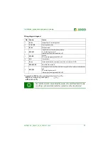
Wiring diagram legend
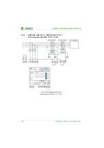
* Explanation:
NC
(in non-operating state closed)
NO
(in non-operating state open)
off
(switched off).
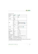
No.
Element
Function
1
A1, A2
Supply voltage
U
s
(see ordering details)
2
L1, L2, L3, N
Power supply connection
3
K1, K2
Relay connections
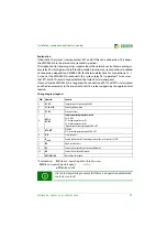
4
DG1/2, D1, D2
Interface switch with contact monitoring
D1: Feedback signal contact K1
D2: Feedback signal contact K2
(
feedback signal contacts optionally NC/NO/off
)*
5
RTG, RT1
RTG: GND
RT1: remote trip input (
optionally NC/NO/off)
*
6
A, B
Service interface
7
R
on/off
Activate or deactivate the terminating resistor of the service interface (120
Ω
)
DG3/4, D3, D4
Not used for these standards
The interface switch is monitored by means of contact feedback. Faulty
conditions such as welded contactor contacts can thus be detected.


