Benchmark
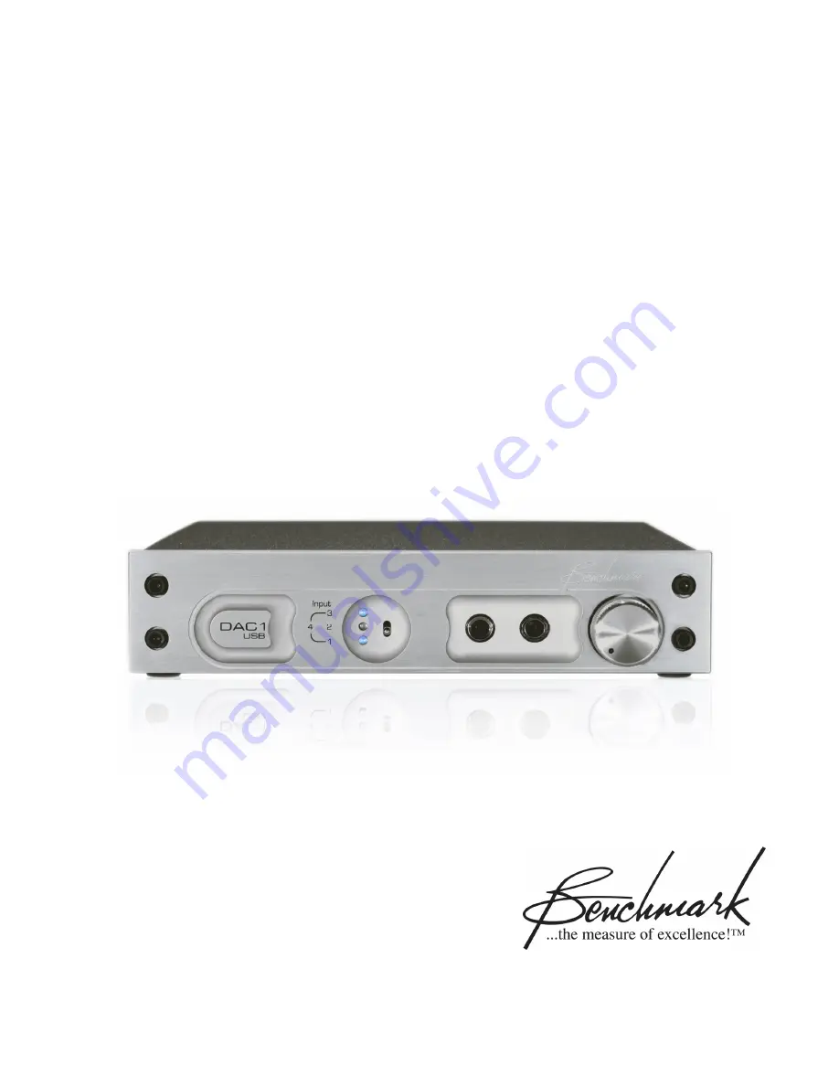
DAC1 USB
Instruction Manual
2-Channel 24-bit 192-kHz
Audio Digital-to-Analog Converter
Page 1: ...Benchmark DAC1 USB Instruction Manual 2 Channel 24 bit 192 kHz Audio Digital to Analog Converter ...
Page 2: ...OPERLY QUALIFIED ONLY A QUALIFIED TECHNICIAN SHOULD PERFORM REPAIRS Fuses CAUTION FOR CONTINUED FIRE HAZARD PROTECTION ALWAYS REPLACE THE FUSES WITH THE CORRECT SIZE AND TYPE 0 5A 250 V SLO BLO 5 X 20 MM LITTELFUSE HXP218 500 OR EQUIVALENT Modifications CAUTION DO NOT SUBSTITUTE PARTS OR MAKE ANY MODIFICATIONS WITHOUT THE WRITTEN APPROVAL OF BENCHMARK MEDIA SYSTEMS INC MODIFICATION MAY CREATE SAFE...
Page 3: ...DAC1 USB Instruction Manual Revision D Page 3 Faceplate Options The DAC1 USB is available with 3 different faceplates The internal electronics are identical in all versions Black Silver Black Rack Mount ...
Page 4: ...t 4 USB 12 Output Level Switch 13 Balanced XLR Analog Line Outputs 13 Unbalanced RCA Analog Outputs 14 Low Impedance Passive Pads 14 Calibration Trimmers 15 AC Power Entry Module 15 Fuse Holder 15 Rack Mounting 16 Rack Mount Coupler 16 Blank Rack Panel 16 Benchmark Technologies 17 HPA2 Headphone Amplifier 17 UltraLock Clock System 18 Advanced USB Audio Technology 21 Performance Graphs 24 Frequency...
Page 5: ... turn y XLR outputs are preset to 4dBu at 0 dBFS in Calibrated mode 20 dB Pad enabled y RCA outputs are preset to 2 Vrms 8 2 dBu at 0 dBFS in Calibrated mode y Headphone jack 1 mutes XLR and RCA outputs feature may be disabled y Benchmark s phase accurate UltraLock technology for total jitter immunity y Status LED s display input selection and error conditions y Automatic Standby Mode activated af...
Page 6: ... is well suited for critical playback in studio control rooms mastering rooms and high end audiophile applications Benchmark s Advanced USB Audio interface makes the DAC1 USB an ideal primary output device for digital audio workstations desktop audio editing applications computer based media playback home media servers and computer based radio broadcast systems The rugged and compact rack mount op...
Page 7: ...brated output levels In Variable mode the analog outputs are controlled by the Volume Control Direct Interfacing to Power Amplifiers The DAC1 USB is designed to interface directly to power amps and powered studio monitors in order to provide the cleanest and shortest path from the digital source to the monitor output This often results in a substantial improvement in sound quality 10 20 and 30 dB ...
Page 8: ...l immediately resume normal operation when an error free signal is restored Low Noise Internal Power Supply The internal power supply supports all international voltages and has generous margins for over and under voltage conditions It has excellent immunity to noise on the AC line and no external AC filtering is required Phase Accurate Multi Track and 5 1 The DAC1 is phase accurate between channe...
Page 9: ...ts 1 Coaxial bottom LED 2 XLR middle LED 3 Optical top LED 4 USB top and bottom LED s When the top and bottom LED s are lit simultaneously the USB Input 4 is selected Error Indication The Input Status Display will flash when an error occurs on the selected digital input The number of times the display flashes before entering standby indicates the type of error If the error is not resolved within a...
Page 10: ...ence with the classic DAC1 showed us that most users cannot use the full output of the HPA2 These users benefit from a reduced maximum gain Internal jumpers reduce the input to the HPA2 by 10 dB and place the Volume Control near 12 O clock at a comfortable listening level with most headphones These jumpers are factory installed but can be removed if a user needs more output Removing the jumpers in...
Page 11: ...ximum word length is 24 bits All sample rates between 28 and 195 kHz are supported The BNC input is DC isolated transformer coupled current limited and diode protected The BNC body is bonded directly to the chassis to prevent currents in the internal ground systems This direct bonding also maximizes RF shielding TIP Shielded 75 Ohm coaxial cable is highly recommended for stable performance Do not ...
Page 12: ...ed to the cable shield Input 3 Optical The optical input connector is manufactured by Toshiba and is commonly known as a TOSLINK connector The TOSLINK optical connector used on the DAC1 USB is designed to work well at sample rates up to 192 kHz Maximum word length is 24 bits All sample rates between 28 and 195 kHz are supported Input 4 USB The USB input accepts a B type male USB 1 1 or USB 2 0 con...
Page 13: ...re muted headphone outputs remain active Variable DOWN Analog output levels are controlled by the Volume Control The Output Level Switch does not affect the operation of the headphone jacks the headphone outputs are never disabled and the headphone level is always controlled from the Volume Control TIP If the DAC1 USB is being used in a critical signal chain such as a broadcast facility or theater...
Page 14: ...bles will generally suffer from hum problems due to ground loops We highly recommend using balanced interconnects for long runs Low Impedance Passive Pads The XLR outputs are equipped with low impedance passive pads that may be used to reduce the output levels while preserving the full dynamic range of the DAC1 USB The DAC1 USB ships with the 20 dB pads enabled TIP When directly driving power ampl...
Page 15: ...The factory preset levels may be increased by 5 dB or decreased by 15 dB in order to conform to other studio reference levels This range of levels is also well suited for direct connection to the balanced line level inputs on most power amplifiers Most professional equipment will work well at these levels Note The Calibration Trimmers have no effect on the output levels when the Output Level Switc...
Page 16: ...Coupler connects the other ear to a wide Blank Rack Panel or another width System1 product TIP Use the rack mount screws supplied with the DAC1 USB or screws with plastic washers to avoid scratching the surface of the faceplate The Rack Mount Coupler and Blank Rack Panel are available from Benchmark Call us visit our website http www BenchmarkMedia com or contact your dealer to purchase these acce...
Page 17: ...ur tests we have measured substantial distortion across resistors that are wired in series with headphones We conducted measurements with a variety of headphones In general distortion increases as headphone impedance decreases This distortion can be eliminated with a properly designed 0 Ohm headphone amplifier The performance of the HPA2 does not change when headphones are driven THD N measurement...
Page 18: ...stage PLL s do not remove enough of the low frequency jitter In addition two stage PLL circuits often require several seconds to lock to an incoming signal Finally a two stage PLL may fail to lock when jitter is too high or when the reference sample frequency has drifted UltraLock converters exceed the jitter performance of two stage PLL converters and are free from the slow lock and no lock probl...
Page 19: ...hat are too high in frequency to be represented at the selected sample rate The not so obvious function is the removal of high frequency signals that originate inside the converter box or even originate inside the converter IC These high frequency signals are a result of crosstalk between digital and analog signals and may have high amplitudes in a poorly designed system Under ideal low jitter con...
Page 20: ...onverters cannot do UltraLock converters cannot undo damage that has already been done If an A D with a jitter problem was used to create a digital audio signal then there is nothing that can be done to remove the damage Jitter induced sidebands are extremely complex and cannot be removed with any existing audio device Therefore it is very important to attack jitter at both ends of the audio chain...
Page 21: ...logy is the first native USB solution capable of streaming 96 kHz 24 bit audio with full bit transparency Beware of Custom Drivers Until now high resolution USB audio devices required custom drivers These drivers may compromise the stability of the operating system and may cause conflicts with other installed devices In addition custom drivers usually consume more system resources memory and CPU t...
Page 22: ...any native USB audio solution so we tested it extensively We found that Kmixer can perform with full or near full bit transparency under the right conditions But under the wrong conditions Kmixer can do a great deal of damage Kmixer s sample rate conversion is of very poor quality under XP and 2000 and must be avoided Benchmark s Advance USB Audio solution allows Kmixer to default to a transparent...
Page 23: ...ixers increase the word length of the audio The longer word length is a result of multiplication and addition These arithmetic operations produce long word lengths that must be squeezed back into a shorter word length Word length reduction adds noise and or distortion to the audio The amount that is added is determined by the output word length The noise and or distortion added by word length redu...
Page 24: ...aphs show the frequency response of the DAC1 when it is operating at a 48 kHz sample rate The top graph shows that the differential phase is better than 0 5º at 20 kHz The bottom graph shows the amplitude response on a highly expanded 0 05 dB division scale The amplitude response is down by only 0 22 dB at 20 kHz The bass response extends well below the 10 Hz limitation of the measurement equipmen...
Page 25: ...ple rate The top graph shows that the differential phase is better than 0 5º at 20 kHz and better than 1º at 43 kHz The bottom graph shows the amplitude response on a highly expanded 0 05 dB division scale The amplitude response is down by only 0 22 dB at 20 kHz and only 1 dB at 43 kHz The bass response extends well below the 10 Hz limitation of the measurement equipment ...
Page 26: ...6 FFT Analysis of Idle Channel Noise The above graph demonstrates that the DAC1 is free from idle tones and clock crosstalk The highest spurious tone measures 128 dBFS and is AC line related hum The highest non line related tone measures 138 dBFS ...
Page 27: ... differential phase between 10 audio channels using 5 DAC1 converters operating at 96 kHz The DAC1 converters were chosen from stock at random and measurements were made using a random combination of Coaxial XLR and Optical inputs The type of digital interface used has no measurable effect on the phase Please note that no reference or synchronization cables are required to create a phase accurate ...
Page 28: ...the variation from 20 Hz to 20 kHz is very slight Note that at worst case the distortion is 109 dB less than the 3 dBFS test tone and 112 dB less than the full scale output of the DAC1 This implies that the distortion created by the DAC1 should be below the threshold of hearing unless playback levels exceed 112 dB peak SPL Distortion should still be well masked at higher playback levels ...
Page 29: ...struction Manual Revision D Page 29 THD N vs Level at 1 kHz Balanced Outputs Below 4 dBFS distortion is lower than the noise floor of the converter Above 3 dBFS distortion reaches a maximum value of only 107 dBFS ...
Page 30: ...phone Outputs This graph shows the output of the HPA2 headphone amp driving a 60 Ohm load at a very high level 14 dBu Even under these conditions the HPA2 delivers the full rated performance of the DAC1 Compare this to the performance of the balanced outputs see previous graph ...
Page 31: ...tion Manual Revision D Page 31 THD N vs Level at 1 kHz Unbalanced Outputs This graph demonstrates the performance of the unbalanced outputs Note that the performance is nearly identical to that of the balanced outputs ...
Page 32: ...Page 32 THD N vs Sample Frequency The above graph shows that the DAC1 provides consistent performance at all sample rates Distortion is not a function of sample rate The minor variations in the above plots are due to measurement limitations ...
Page 33: ...r the top curve is on the right hand side of the graph and is calibrated in UI of jitter The bottom green curve shows the THD N of the DAC1 as the jitter amplitude and frequency is varied at the inputs of the DAC1 There is absolutely no change in the DAC1 THD N measurement over the entire range of jitter test frequencies and amplitudes In fact the DAC1 can tolerate much higher levels of jitter wit...
Page 34: ...ze the sensitivity of the test We set the interface jitter amplitude to its maximum value of 12 75 UI 2075 ns of jitter We then swept the jitter frequency from 2 Hz to 9 kHz and plotted the THD N from the DAC1 Absolutely no change in THD N was observed at any test frequency and the DAC1 performance did not change when the jitter was turned off The same test was conducted using FFT analysis to look...
Page 35: ...ion Manual Revision D Page 35 Immunity to Cable Induced Jitter The above FFT plots demonstrate that the performance of the DAC1 is not degraded in any way when long cables are used to transmit digital audio to the DAC1 ...
Page 36: ...Input Sensitivity Tests XLR Digital Input Sensitivity The above graph shows that the performance of the DAC1 is not a function of the signal level at the XLR digital input When the signal is too low to decode 160 mVpp the converter mutes gracefully ...
Page 37: ...Page 37 Coaxial Digital Input Sensitivity The above graph shows that the performance of the DAC1 is not a function of the signal level at the coaxial digital input When the signal is too low to decode 120 mVpp the converter mutes gracefully ...
Page 38: ... the AES In addition the above plots show that while the AES minimum eye pattern specifications are barely met at the end of 1000 feet of Category 5 UTP cable the DAC1 receivers have enough sensitivity to allow reliable operation The jitter produced by this connection is removed entirely by the Benchmark UltraLock clock circuits and the DAC1 operates at full specified performance ...
Page 39: ...e 39 Volume Control Curve Volume Control 80 0 70 0 60 0 50 0 40 0 30 0 20 0 10 0 0 0 10 0 0 5 10 15 20 25 30 35 40 Rotation Steps Gain dB Volume Control Step Size 0 1 2 3 4 5 6 7 8 9 10 0 5 10 15 20 25 30 35 40 Rotation Steps Step Size dB Step ...
Page 40: ...107 dB 0 00045 THD N 20 to 20 kHz test tone at 3 dBFS 110 dBFS 107 dB 0 00045 Frequency Response at Fs 96 kHz 0 1 dB 20 to 20 kHz 0 02 dB at 10 Hz 0 20 dB at 20 kHz 0 85 dB at 40 kHz 2 5 dB at 45 kHz Frequency Response at Fs 48 kHz 0 1 dB 20 to 20 kHz 0 02 dB at 10 Hz 0 20 dB at 20 kHz Crosstalk 100 dB at 20 kHz 125 dB at 1 kHz 130 dB at 20 Hz Maximum Amplitude of Jitter Induced Sidebands 10 kHz 0...
Page 41: ...p Down Time 10 ms Mute on Receive Error Yes Mute on Lock Error Yes Mute on Idle Channel No 50 15 us De Emphasis Enable Automatic in Consumer Mode De Emphasis Method Digital IIR De Emphasis Supported at Fs 32 44 1 48 and 96 kHz Group Delay Latency Delay Digital Input to Analog Output function of sample rate The delay can be calculated using the following formula Delay 1 01 ms 48 Fs Where Fs the sam...
Page 42: ...l input jumper selected 75 Ohms or Hi Z Bridging Transformer Coupled Digital Inputs Yes Coaxial XLR Optical DC Blocking Capacitors on Digital Inputs Yes Coaxial XLR Optical Transient and Over Voltage Protection on Digital Inputs Yes Minimum Digital Input Level 300 mVpp on XLR 150 mVpp on Coaxial Jitter Tolerance With no Measurable Change in Performance 12 75 UI sine 100 Hz to 10 kHz 3 5 UI sine at...
Page 43: ...Range at 0 dBFS In Variable Mode Off to 29 dBu Attenuator off Off to 19 dBu Attenuator 10 dB Off to 9 dBu Attenuator 20 dB Off to 1 dBu Attenuator 30 dB Output Level Variation with Sample Rate 44 1 kHz vs 96 kHz 0 006 dB Unbalanced Analog Outputs Number of Unbalanced Analog Outputs 2 Output Connector RCA Output Impedance 30 Ohms Output Level Calibration Controls Shared with Balanced Outputs Output...
Page 44: ...pendent per channel Current limited at 300 mA Thermal Bandwidth 500 kHz THD N 106 dB 0 0005 into 30 Ohms at 18 dBu 1 26W Status Display Indicators Type and Location 3 Blue LED s on Front Panel Selection Status Indication Solid Digital Input Selection Flashing Signal Error None Standby Mode AC Power Requirements Input Operating Voltage Range VAC RMS 110 V setting 90 V min 140 V max 220 V setting 17...
Page 45: ...Overall depth including connectors but without power cord or BNC to RCA adapter 9 33 237 mm Width 9 5 249 mm Height 1 725 44 5 mm Weight DAC1 USB only 3 5 lb DAC1 USB with power cord 3 BNC to RCA adapters extra fuses and manual 4 5 lb Rack mount kit blank panel junction block and rack mount screws 0 32 lb Shipping weight 7 lb ...
Page 46: ...ll not occur in a particular installation If this equipment does cause harmful interference to radio or television reception which can be determined by turning the equipment off and on the user is encouraged to try to correct the interference by one or more of the following measures Reorient or relocate receiving antenna Increase the separation between the equipment and receiver Connect the equipm...
Page 47: ...DAC1 USB Instruction Manual Revision D Page 47 CE Certificate of Conformity ...
Page 48: ...pairs will be billed at the normal shop rate In such cases an estimate will be submitting before work is started if requested by the customer Attempts to deliberately deface mutilate or remove the product s label will render this warranty void Any DAC1 USB returned from the European Union for warranty repair must have the required RoHS logo on the product label otherwise repairs will be billed at ...
Page 49: ... Media Systems Inc optionally extends the standard one 1 year warranty to a period of two 2 years from the date of delivery For the extended warranty to become effective the original purchaser must register the product at the time of purchase either by way of the prepaid registration card or through the product registration section of the Benchmark Media Systems Inc website This optional warranty ...
Page 50: ...e jumper configured 10 dB Headphone Gain Reduction Headphone Switch Disable XLR Output Pads Default Digital Input Coaxial Input Termination A 2 pin jumper plug at header P2 can be moved in order to select a default input which will be selected upon each power up A jumper at JP7 can be removed to disable the 75 Ohm termination on the coaxial digital input Four 8 pin headers P4 P5 P6 and P7 allow se...
Page 51: ...efault Photo 2 BNC Input Termination JP7 XLR Output Pad Selection P4 P5 P6 and P7 One pair of 8 pin headers controls the output level at each XLR jack as follows 0 dB Attenuator disabled Jumper plug between pins 1 and 2 of each header 10 dB Jumper plug between pins 3 and 4 of each header 20 dB Jumper plug between pins 5 and 6 of each header 30 dB Jumper plug between pins 7 and 8 of each header Fac...
Page 52: ... front panel Volume Control above 40 10 o clock without the headphone volume being too loud JP8 and JP9 are factory installed to reduce the headphone output by 10 dB This setting is best for most applications Remove the jumpers if you need more gain Photo 4 Headphone Gain Reduction JP8 and JP9 Copyright 2007 Benchmark Media Systems Inc All rights reserved Benchmark Media Systems Inc 5925 Court Str...