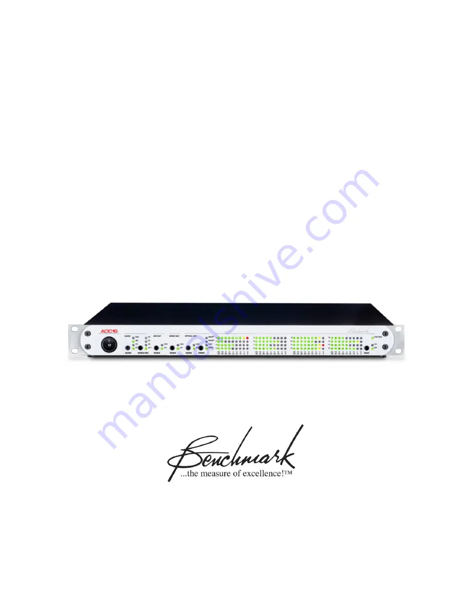
Benchmark ADC16
Instruction Manual
16-Channel 24-bit 192-kHz
Audio Analog-to-Digital Converter
Page 1: ...Benchmark ADC16 Instruction Manual 16 Channel 24 bit 192 kHz Audio Analog to Digital Converter...
Page 2: ...lanced Analog Audio Inputs 22 WC SC AES Clock Reference Input 22 AES Clock Reference Input 22 Balanced AES EBU Digital Outputs 23 Coaxial Digital Outputs 23 Multi Format Optical Digital Outputs 23 DAW...
Page 3: ...ord Clock output is active in all modes of operation A multi format clock input automatically recognizes AES EBU SPDIF Word Clock or Super Clock signals This clock input is used to synchronize the dig...
Page 4: ...raLockDDS meets or exceeds the performance of Benchmark s UltraLock system but does not use asynchronous sample rate conversion ASRC The elimination of the ASRC processing reduces system latency and p...
Page 5: ...inout 6 dBu to 29 dBu input sensitivity range at 0 dBFS 10 turn gain calibration controls 1 per channel with a 23 dB gain range Press and hold buttons to prevent catastrophic incidents Sample rate sel...
Page 6: ...tatus Indication page 9 Lock Status Reference Sample Rate Error Reporting Source for Digital Outputs page 10 Settings Source Internal A D Converters Source DAW Card Optical Output Format page 11 Setti...
Page 7: ...ch disconnects both sides of the AC line When this switch is OFF the ADC16 draws no power When this switch is turned ON the ADC16 will boot up and calibrate within 5 seconds User settings are automati...
Page 8: ...k reference for the ADC16 The indicators are as follows DAW On clock is locked to the optional interface card AES On clock is locked to the AES EBU input via DB 25 WC On clock is locked to the WC inpu...
Page 9: ...of the following ranges 28 50 kHz 75 100 kHz or 150 kHz 200 kHz Clock Error No Reference Clock Source LED flashing once per second and INT LED ON If no signal is present on the selected clock input th...
Page 10: ...s using any of the digital audio outputs on the ADC16 In such a system it is not necessary to purchase a DAW interface for the D A converters The ADC16 provides the interface between the DAW and the e...
Page 11: ...ADAT format The AES EBU mode works with most S PDIF optical inputs Press and hold the FORMAT button to change the optical output format The press and hold action prevents accidental changes When ADAT...
Page 12: ...ining LEDs will follow the instantaneous level of the audio The red 0 LED indicates that a full scale digital code has been reached and that digital clipping has occurred Full scale events as short as...
Page 13: ...page 16 Tascam AES EBU DB 25 Standard Pinout 2 Connectors 16 Channels Out 2 Channels In Coaxial Digital Audio Outputs page 17 AES Professional Format 1Vpp Coaxial Outputs 16 Channels Out Optical Digi...
Page 14: ...14 Slot for Optional Interface Cards page 19 See http www BenchmarkMedia com ADC16 optional interface card AC Power Entry Connector page 19 IEC Power Connector Fuse Holder page 19 Requires two 0 5 Amp...
Page 15: ...out The ANALOG IN DB 25 pinout follows the Tascam Analog DB 25 standard H or hot C or cold G GND Unbalanced Source Adaptation 1 Connect or hot tip on phone plug center pin on RCA plug 2 Connect both t...
Page 16: ...h set of outputs AES I O S PDIF and Optical has a SOURCE selection button These may be used in any combination When DAW is selected as the source the user can assign any tracks or sub mixes of tracks...
Page 17: ...d and diode protected They incorporate filtering to minimize RF interference and susceptibility Data Format AES EBU professional Word Length 24 bits Sample Rate 28 to 50 kHz 75 to 100 kHz and 150 kHz...
Page 18: ...d for 16 channels of audio The 8 optical connectors on the ADC16 carry two identical sets of data when operating in ADAT S MUX2 ADAT S MUX4 is available at sample rates between 150 and 200 kHz In this...
Page 19: ...ble as a studio master clock Slot for Optional Interface Cards An interface card can be installed in the ADC16 The card is installed in the slot to the left of the AC power input This slot provides a...
Page 20: ...20 kHz 0 06 dB at 10 Hz 0 01 dB at 20 Hz 0 02 dB at 20 kHz 0 10 dB at 44 kHz 3 dB at 47 3 kHz 115 dB at 54 kHz Frequency Response at Fs 48 kHz 3 dB 0 dB 1 Hz to 23 6 kHz 0 01 dB 20 Hz to 20 kHz 0 06 d...
Page 21: ...25 degrees at 20 kHz Maximum Lock Time after Fs change 8 seconds Mute on Sample Rate Change Yes less than 8 seconds duration Mute on Loss of External Clock Yes after 5 seconds of no clock Mute on Lock...
Page 22: ...uency RF Filter Transient Protection Over Voltage Protection AC Coupled WC SC AES Clock Reference Input Connector Input Impedance Input Formats Auto Detected Sensitivity with Word Clock Input Sensitiv...
Page 23: ...Output Sample Rate Output Word Length Connectors Output Impedance Output Level 16 AES3 Professional Data Format Up to 200 kHz 24 bits Eight RCA Connectors 75 1 Vpp into 75 Transformer Coupled DC Block...
Page 24: ...yed response push and hold allows shared use of the meter SCALE button Status Indicators Clock Source Sample Rate AES Output Source Coaxial Output Source Optical Output Source Optical Format Meter Ran...
Page 25: ...Page 25 Dimensions Form Factor Depth Behind Front Panel Recommended Minimum Rack Depth to Clear Cables Depth Width Height 1 Rack Wide 1 RU High 12 125 16 12 5 19 1 725 Weight ADC16 only Shipping Weig...
Page 26: ...so be mistaken for S MUX2 and could be played at of its original sample rate Please note that these changes in sample rate will not alter the pitch of the audio but will introduce errors and these err...
Page 27: ...rface but the recorder must be set to the audio sample rate if S MUX2 is in use or the audio sample rate if S MUX4 is in use S MUX Must Not be Used for SRC If two devices are connected with an ADAT S...
Page 28: ...annel 7 Audio Channel 4 a ADAT Channel 8 Audio Channel 4 b X a and X b are successive samples of audio channel X ADAT S MUX4 Channel Assignments ADAT Channel 1 Audio Channel 1 a ADAT Channel 2 Audio C...
Page 29: ...the most direct path from the A D to the digital interface Does my system have a jitter problem Jitter is present on every digital audio interface This type of jitter is known as interface jitter and...
Page 30: ...IMD Like IMD jitter induced distortion is much more audible than harmonic distortion and more audible than THD measurements would suggest Jitter creates new audio that is not harmonically related to...
Page 31: ...mulate throughout even the most carefully designed digital audio system Fortunately interface jitter can only degrade digital audio if it affects the sampling circuit in an analog to digital or digita...
Page 32: ...ADC16 Instruction Manual Page 32 Regulatory Compliance CE Certificate of Conformity...
Page 33: ...ed at the normal shop rate In such cases an estimate will be submitted before work is started if requested by the customer Attempts to deliberately deface mutilate or remove the product s label will r...
Page 34: ...card or through the product registration section of the Benchmark Media Systems Inc website This optional warranty applies only to products purchased outside the US and Canada and is extended only to...
Page 35: ...e 35 Contact Information Benchmark Media Systems Inc 203 East Hampton Pl Suite 2 Syracuse NY 13206 USA 1 315 437 6300 FAX 1 315 437 8119 http www benchmarkmedia com Copyright 2011 Benchmark Media Syst...