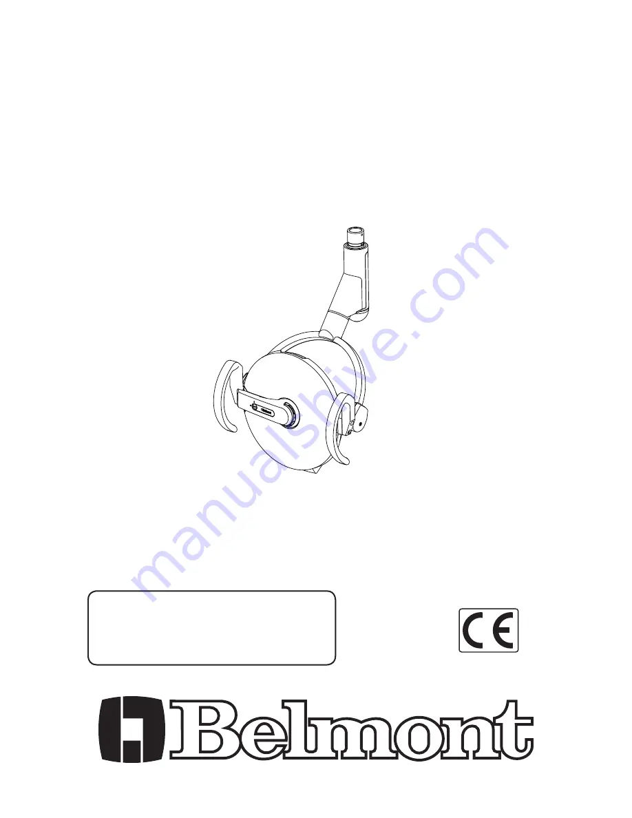
INSTALLATION
AND
OPERATION
INSTRUCTIONS
DENTAL LIGHT
IMPORTANT
After installation is completed, check all
the bolts, screws and fasteners to confirm
that they are securely fastened.
TYPE AL-820S
IO 5000TA
Page 1: ...NSTALLATION AND OPERATION INSTRUCTIONS DENTAL LIGHT IMPORTANT After installation is completed check all the bolts screws and fasteners to confirm that they are securely fastened TYPE AL 820S IO 5000TA...
Page 2: ......
Page 3: ...e 4 8 ADJUSTMENT OF THE BALANCE ARM 8 1 Adjustment of the tension of the balance arm 5 8 2 Adjustment of the angle of the light head 5 8 3 Adjusting the tension of the light head 6 8 4 Balance arm adj...
Page 4: ...peration and accidents In case of disposal of equipment When disposing the dental light appropriately dispose complying with all current applicable regulations and local codes In EU area EU directive...
Page 5: ...ould be conducted by an authorized installation service personnel only WARNING The followings are prohibited To modify this equipment To use the equipment under any failure condition To use the equipm...
Page 6: ...ctly connected During use Do not use the light longer than required for examination or treatment Always watch the patient and the equipment to make sure nothing is wrong If anything wrong is observed...
Page 7: ...ht Pole Joint Balance Arm Joint Arm Joint Cover Balance Arm Arm Joint Cover Yoke Joint First Yoke LED Second Yoke Intensity Switch Handle Left Touchless Sensor Switch Reflector Cover Light Bulb Cover...
Page 8: ...ernate Intensity Selection Momentary SV2P Power Input 1 2 CN1 CN8 VH4P 1 4 3 2 1 2 Red Black Brown Setting of PCB Dip Switch SW1 1 2 3 4 OFF OFF ON ON OFF OFF OFF 4 3 2 1 SW2 Off Disable On Enable Def...
Page 9: ...n instruction of the unit Light Cable Light Head Light Pole Button Screw M6x8 Light Pole Joint 6 3 Connect the wire harness Fig 6 3 Attach the connectors of the light cable onto the dental light PCB a...
Page 10: ...ce and hold your hand within the reaction zone for 2 seconds The light intensity will be automatically reduced to the composite mode To switch back to the normal treatment mode place your hand by the...
Page 11: ...g the socket screw will damage the arm 2 Position the angle of the balance arm so the head angle adjustment nut becomes visible just under the slot C Turn the nut and adjust the tension with the adjus...
Page 12: ...w to adjust 1 Loosen the four M5 socket head screws E with the supplied 2 5mm Allen key When adjusting make sure that the socket head screws are loosened Failure to do so may cause damage to the threa...
Page 13: ...end of the upper side of the light pole joint and move the balance arm in place 7 Loosely tighten both top and bottom M8x20 D screws 8 Tighten both top and bottom M8x20 D screws and adjust the lateral...
Page 14: ...y after the lamp goes off Wait until they get cool down Do not touch glass with bare hand Halogen bulb surface must be clean Oil or body moisture will affect bulb span of life If glass surface is touc...
Page 15: ...the reflector cover 1 Insert the cut out of the reflector cover into the gap at the handle right See Fig 9 4 1 2 Be careful not to pinch the wires when attaching cover See Fig 9 4 2 3 Hold the reflect...
Page 16: ...d be taken to prevent scratching reflector surfaces as this will degrade the performance of the light CAUTION All surfaces can be cleaned with DURR FD333 cleaner Spray the cleaner DURR FD333 on cloth...
Page 17: ...ore start Swing the balance arm up down Swing the balance arm right left Make sure the balance arm stops and holds its position Light head doesn t stay at the desired position Adjust the tension of th...
Page 18: ...aken upon checkup stated above then stop using the unit turn off the main switch and contact your dealer or our of ce Unit main switch is not on Turn on the unit main switch The light does not light u...
Page 19: ...ser of the IO5000TA should assure that it is used in such an environment Immunity test IEC 60601 test level Compliance level Electromagnetic environment guidance Electrostatic discharge ESD IEC 61000...
Page 20: ...tromagnetic site survey a should be less than the compliance level in each frequency range b Interference may occur in the vicinity of equipment marked with the following symbol NOTE 1 At 80 MHz and 8...
Page 21: ...istance according to frequency of transmitter m 150 kHz to 80 MHz d 1 2 P 80 MHz to 800 MHz d 1 2 P 800 MHz to 2 5 GHz d 2 3 P 0 01 0 12 0 12 0 23 0 1 0 38 0 38 0 73 1 1 2 1 2 2 3 10 3 8 3 8 7 3 100 1...
Page 22: ......
Page 23: ......
Page 24: ...4RC0 2 1 1 Higashishinsaibashi Chuo ku Osaka 542 0083 Japan TEL 81 6 6213 5945 FAX 81 6 6212 3680 TAKARA BELMONT CORPORATION Takara Belmont U K Ltd Belmont House One St Andrews Way Bow London E3 3PA U...