background image

19

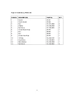
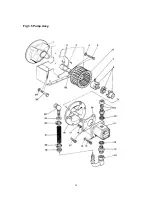
3.5.7. - ENGINE - Refer to Fig 3.5.

a)

Remove the Fan as described in 3.5.6..

b)

Remove the 4 off bolts (Item 23) securing the engine to the Tank, remember to support the
weight of the Engine Spacer (Item 1).

c)

Remove the 4 off Set Screws (Item 14 Fig 3.1) to release the Engine from the Chassis.

d)

The Engine can now be lifted clear of the Tank/Chassis.

NOTE

:- If an engine replacement is necessary the Shaft Extension fitted to the Engine shaft must be

taken off by removing the Retaining Bolt (Item 4). The Shaft Extension can then be slid off the engine
shaft once the Grub Screws (Item 2) have been unscrewed.

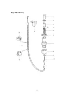
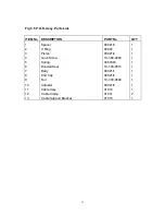
3.5.8. - POWER ON DEMAND SYSTEM - Refer to Fig 3.6.

NOTE -

 The P.O.D. Cylinder and cable assy are designed as a cartridge which can be disassembled

completely without disturbing any other part of the Power Pack.

a)

Slacken the P.O.D. Retaining Nut (Item 8) and unscrew fully.

b)

Pull down the Nut/Cable to extract the Spring (Item 5) and Piston (Item 3) for examination.

NOTE 

- To connect a new Cable the piston can be withdrawn sufficiently to reveal the Grub Screw

(Item 4) which clamps the cable to the piston allowing access without extracting the 'U' Ring (Item 2)
from the body.

c)

The P.O.D. Body (Item 7) can be unscrewed from the Valve Block for examination if desired.

d)

The Cable can only be removed from the Tank by removal of the Clamps (Item 12). These
clamps are plastic and cannot be removed without damage. Replace the clamps upon
reassembly.

NOTE -

 Reassembly is the reverse of the above procedure. However, care should be taken when

fitting the Piston Seal (Item 2) into the bore of the body (Item 7). Standard cable length allows for the
cable to be pushed fully home into the piston before clamping by the grub screw (Item 4).

When unit is fully reassembled adjuster (item 10) can be adjusted as follows:-

Adjustment

a)

Start engine with cable slack and check flow and pressure as per section 3.4.

b)

Off load the machine by operating the By-pass lever.

c)

Adjust the cable tightness by using the adjuster (item 10) until the engine speed drops to 
1800-2200 rpm.

d)

lock off adjuster and check that engine reaches high speed when system pressure is raised

e)

Repeat if settings are not as specified.

Summary of Contents for Major 30-140

Page 1: ...AULIC POWERPACK OPERATING AND MAINTENANCE MANUAL Belle Group Willersey Willersey Industrial Estate Willersey Nr Broadway Worcestershire England Issue No 2 Telephone 44 0 1386 858482 Date NOV 2002 Fax 44 0 1386 858378 email Tech panther ltd com ...

Page 2: ...structions 3 Maintenance 4 Parts Lists 5 Safety A comprehensive Contents list follows this foreword Information contained in this manual is correct at the date of publication Belle Group Willersey have a policy of continuous improvement and therefore reserve the right to make alterations without giving prior notice The contents of this manual are copyright C and must not be reproduced without prio...

Page 3: ...tion which if ignored could cause FOR YOUR OWN PERSONAL SAFETY READ AND TAKE NOTE OF THE FOLLOWING EXHAUST GASES Before starting the engine ensure that there is adequate ventilation to REFUELLING Never attempt to add fuel or oil when the engine is running Use only the MAINTENANCE Do not attempt to carry out any maintenance work in the vicinity of the Before disconnecting any part of the hydraulic ...

Page 4: ...NTRODUCTION 3 1 1 Maintenance Procedure Recommendations 3 2 ROUTINE MAINTENANCE 3 2 1 Routine Maintenance Schedule 3 3 FAULT DIAGNOSIS 3 4 SYSTEM PRESSURE AND FLOW CHECKS 3 5 REMOVAL AND REFITTING PROCEDURES 3 5 1 Frame Chassis Assy 3 5 2 Cowl 3 5 3 Valve Block 3 5 4 Cooler 3 5 5 Pump 3 5 6 Fan 3 5 7 Engine 3 5 8 Power on Demand System SECTION 4 PARTS LISTS 4 1 SPARES HOLDING INFORMATION 4 2 SPARE...

Page 5: ...st estate cars The stainless steel frame provides convenient handling points and protects the unit Non drip Quick Release Couplings are provided to allow for clean and convenient connection of hoses and equipment The unit is mounted on a substantial steel chassis fitted with two rubber wheels and two rubber feet making the unit very maneuverable yet stable when working The unit is powered by the r...

Page 6: ...start up the oil is cold and therefore its viscosity is high The Thermal Valve directs the oil to tank until such time as the oil temperature rises to its minimum working level The Thermal Valve which incorporates a heat sensitive capsule will now direct the return line oil flow to tank via the cooler thereby stabilizing the oil temperature Cooling air for the radiator is provided by a fan which i...

Page 7: ...138 Bar 2000 Psi Dimensions Height 560 mm Width 540 mm Length 720 mm Hose 7 metres long Siamese 1 2 bore min Burst Pressure 828 Bar 12000 Psi Hydraulic Oil For ambient Temperatures below 32 degrees Centigrade use a ISO VG T32 or equivalent For ambient Temperatures above 32 degrees Centigrade use ISO VG T46 or equivalent Fuel Petrol Unleaded Tank Capacity 6 5 Litres Guaranteed Noise Level 104 LWA ...

Page 8: ...t gases 3 Ensure that the transmission hoses are positioned to avoid damage by vehicles etc and that they will not be under strain when connected to the accessory or tool CAUTION ENSURE THAT THE INTERCONNECTING HOSE COUPLINGS ARE DAMAGE TO SEALS WARNING NEVER ATTEMPT TO ADD FUEL OR OIL WHEN THE ENGINE IS RUNNING USE ONLY THE CORRECT GRADE AND DO NOT OVERFILL 4 Check engine fuel and oil level top u...

Page 9: ...checks should be made 1 By Pass lever is in the flow position 2 Check that there is no excessive engine vibration 3 Ensure that there are no hydraulic leaks from hoses or couplings 4 Check that the filter condition indicator is not within the clogging sector once normal Depending on the ambient temperature optimum performance should be achieved after 5 10 minutes operation This is the time require...

Page 10: ...All parts should be laid out on a clean surface and their identification and dismantling sequence noted d All dismantled metal components should be cleaned using a mineral based solvent dried and then coated with clean hydraulic oil Seals should be washed with clean hydraulic oil It is recommended that removed seals should be discarded and replaced with new items Where a seal is to be refitted it ...

Page 11: ...k for correct positioning of protective sleeve Engine Check oil level Examine engine mountings Examine Exhaust silencer for damage or deterioration Check for excess vibration when running Change Oil Service Refer to manufacturers instructions Hydraulic Tank Check oil level Replace Filter Change Hydraulic Oil Oil Cooler Externally clean using compressed air DO NOT USE WIRE BRUSH Return line Filter ...

Page 12: ...re Para 3 4 Renew pump if necessary Refer to engine manual Hydraulic oil temperature too high Radiator fins blocked Cooling fan lose or damaged Hydraulic pump worn or damaged Relief valve set low or worn Thermal valve malfunction Hydraulic oil contaminated Clean using air blast Tighten or renew as necessary Renew pump Check setting replace as necessary Renew valve Drain oil tank transmission hoses...

Page 13: ...ass lever to the flow position Close the load valve completely and check that the relief valve setting is correct 140 Bar The hydraulic oil will tend to get quite hot during this operation and therefore the checking should be carried out as quickly as possible and the load valve opened before excessive temperatures are reached 3 Carefully close the load valve to raise the pressure to 100 Bar 1500 ...

Page 14: ...ue to damage etc The handle is riveted to the frame using a strong rivet Item 2 which is installed at the factory using a special tool Replacement of these rivets cannot easily be made without the special tool and we recommend that this operation is carried out by the Belle Group Willersey Service Department d The two Universal Mounting Plates Item 12 can be removed by undoing the Set Screws Item ...

Page 15: ...R C Couplings Fig 3 3 Items 17 18 taking care not to damage the gasket Item 13 g Access is now available to the inside of the tank allowing removal of the Suction Strainer Item 2 Float Switch Item 6 and Sight Level Gauge Item 5 for servicing NOTE It is recommended that a new Gasket Item 13 drain plug seal Item 3 and Gauge seal Item 15 be fitted upon reassembly NOTE The Tank Item 1 should not norma...

Page 16: ...wrench may be used provided that the Can is not distorted 2 The Relief Valve Item 11 is a cartridge unit and should only be removed to examine the seals fitted to the nose If problems arise regarding pressure control it is advisable to fit a new Relief Valve 3 Should any hydraulic fittings and bonded seals be removed it is advisable to refit using new seals after examining the fitting to ensure th...

Page 17: ...lic oil d Unscrew the 6 off screws Item 5 and 2 off Screws Item 13 holding the cooler Item 1 and Guard Item 2 to the fan housing and retain the Nuts Item 3 and Washers Item 4 e Gently pull the Cooler from its housing complete with Guard and separate NOTE Refitting the cooler assy is the reverse of the above however it should be noted that the cooler is manufactured from soft materials and should t...

Page 18: ...Washer and removing the Nut The coupling half will usually require a puller for removal as it is prone to locking on its taper The port connectors Items 9 12 must also be removed NOTE Refitting the pump is the reverse of the above however it is recommended that new Bonded Seals Item 10 are fitted taking care to ensure that the port adaptors are not damaged 3 5 6 FAN Refer to Fig 3 5 a Remove the p...

Page 19: ... piston can be withdrawn sufficiently to reveal the Grub Screw Item 4 which clamps the cable to the piston allowing access without extracting the U Ring Item 2 from the body c The P O D Body Item 7 can be unscrewed from the Valve Block for examination if desired d The Cable can only be removed from the Tank by removal of the Clamps Item 12 These clamps are plastic and cannot be removed without dam...

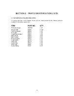
Page 20: ...lable for immediate replacement ITEM PART NO QTY Pressure Gauge 00005 2 1 off Gauge Seal 00006 10 off Tank Lid Gasket 00858 1 off Oil Cooler 01414 1 off Valve Block Gasket 00803 1 off QRC Probe 00545 2 off QRC Carrier 00546 2 off Drive Coupling 01453 1 off Float Switch 00790 1 off Filter Can 00178 1 off Cable Assy 01014 1 off POD Assy 00921 1 off Cable Clamp 01031 2 off ...

Page 21: ...warranty applying to Hoses Couplings and Seals The guarantee covers defects in workmanship or materials under normal use and service Panther agree to repair or replace at their discretion without charge to the purchaser any part or parts proven to be defective within the warranty period This Warranty will not apply a To a Belle Group Willersey Product which has been subject to misuse negligence ac...

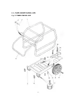
Page 22: ...22 4 3 PARTS IDENTIFICATION LISTS Fig 3 1 FRAME CHASSIS ASSY ...

Page 23: ...Rivet Washer Handle Chassis Chassis Plug Bonded Foot Wheel Durlock Bolt Set Screw Spring Washer Universal Mounting Plate Shakeproof Washer Set Screw Plain Washer 01493 01150 10 400 0800 01476 01436 00013 01525 01524 01419 10 340 1016 10 410 1000 01651 10 405 1000 10 340 1035 10 400 1000 1 2 2 1 1 4 2 2 4 4 4 2 4 4 4 ...

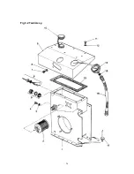
Page 24: ...24 Fig 3 2 Tank Assy ...

Page 25: ...nking Plug Bolt Sight Glass Float Switch Cap Screw Shakeproof Washer Cowl Filler Cap Set Screw Plain Washer Gasket Pressure Gauge Pressure Gauge Seal Capillary Hose Rivet 01654 00065 10 100 0510 10 340 1016 01466 00790 10 330 0810 10 405 0800 01655 00129 10 340 0616 10 400 0600 00858 00005 2 00006 00007 01160 1 1 1 1 1 1 1 1 1 1 8 8 1 1 1 1 12 ...

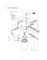
Page 26: ...26 Fig 3 3 Valve Block Assy ...

Page 27: ...le Adaptor Bonded Seal Bonded Seal Adaptor Bonded Seal Q R C Carrier Q R C Probe H P Feed Pipe Nut Adaptor Circlip Filter Spigot Filter Can Set Screw Shakeproof Washer Clamping Plate Blanking Plug Gasket 01392 01392 1 10 202 6347 10 360 0510 00920 2 00920 3 00045 10 500 0515 01082 1 01082 2 01082 3 01082 10 600 0404 10 100 0511 10 100 0513 10 600 0806 10 100 0512 00546 00545 01878 00060 CS 10 600 ...

Page 28: ...28 Fig 3 4 Cooler Assy ...

Page 29: ...9 10 11 12 13 Cooler Cooler Guard Nut Washer Set Screw Cooler Return Pipe Nut Nut Cooler Feed Pipe O Ring Cap Screw Plain Washer Set Screw 01441 01448 10 301 0600 10 400 0600 10 340 0616 01478 00060 00060 01479 10 202 5157 10 330 0810 10 400 0800 10 340 0612 1 1 6 8 6 1 1 1 1 2 1 1 2 ...

Page 30: ...30 Fig 3 5 Pump Assy ...

Page 31: ...n Hose Adaptor Cap Screw Shakeproof Washer Nut Washer Pump Plate Back Up Ring Jubilee Clip Suction Hose Compact Elbow Bolt Shakeproof Washer Key Pump Conversion Plate Cap Screw 01963 10 360 0610 01660 10 405 1000 10 321 0652 01391 10 360 0810 01653 01034 10 100 0513 02151 10 600 1208 00051 10 330 0835 10 405 0800 10 301 0800 10 400 0800 00490 00052 10 501 2540 01659 01140 10 321 0537 10 405 0800 0...

Page 32: ...32 Fig 3 6 P O D Assy ...

Page 33: ... 6 7 8 9 10 11 12 13 Spacer U Ring Piston Grub Screw Spring Bonded Seal Body End Cap Nut Adjuster Cable Assy Cable Clamp Cable Support Bracket 00921 3 00922 00921 2 10 360 0404 0067863 10 100 0513 00921 1 00921 4 10 300 0600 00921 5 01014 01031 01015 1 1 1 1 1 1 1 1 1 1 1 2 1 ...

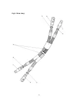
Page 34: ...34 Fig 3 7 Hose Assy ...

Page 35: ...35 Fig 3 7 Hose Assy Parts List ITEM No DESCRIPTION PART No QTY 1 2 3 4 Q R C Probe Bonded Seal Hose Assy Q R C Carrier 00545 10 100 0512 00560 00546 2 4 1 2 ...

Page 36: ...03 103 135 180 172 138 138 138 138 138 180 If in doubt consult the equipment manufacturer Characteristics Operators not familiar with use of hydraulic power packs should note the following points 1 Hydraulic power units use oil to transmit power hence it is essential to only use hydraulic oil of the type and grade recommended by the manufacturer Also ensure that the correct oil level is maintained...

Reviews: