10
SECTION 3 - MAINTENANCE.
3.1 - INTRODUCTION.
In this section information on maintenance of the power unit is presented in the form of a Routine
Maintenance Schedule followed by a Fault Location Chart, and inspections and specific maintenance
instructions of the power unit assemblies.
3.1.1 - MAINTENANCE PROCEDURE RECOMMENDATIONS.
Before carrying out any maintenance on the power unit note the following recommendations:-
a)
The hydraulic components used on Belle Group units are precision made; maintenance of
these components should therefore be carried out by suitably qualified personnel.
b)
When servicing hydraulic components, absolute cleanliness is essential. Most hydraulic faults
are caused by the ingress of dirt.
c)
Before dismantling a component, clean externally and drain all fluid. All parts should be laid
out on a clean surface and their identification and dismantling sequence noted.
d)
All dismantled metal components should be cleaned using a mineral based solvent, dried and
then coated with clean hydraulic oil. Seals should be washed with clean hydraulic oil. It is
recommended that removed seals should be discarded and replaced with new items. Where
a seal is to be refitted it must be closely inspected for wear or damage and if suspect must
not be reused.
e)
Do not use pipe wrenches on hose connections, as they damage fittings and protective
plating. Use adjustable or open-ended spanners. When tightening hose connections ensure
that the hose does not become twisted.
3.2 - ROUTINE MAINTENANCE.
The following schedule details the attention considered necessary to ensure satisfactory operation of
the power unit.
NOTE :
THE ATTENTIONS AND PERIODS SUMMARISED IN THE SCHEDULE ARE
INITIAL RECOMMENDATIONS AND SHOULD BE REVISED TO SUIT THE
POWER UNIT WORKING CONDITIONS.
Summary of Contents for Major 30-140
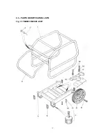
Page 22: ...22 4 3 PARTS IDENTIFICATION LISTS Fig 3 1 FRAME CHASSIS ASSY ...
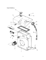
Page 24: ...24 Fig 3 2 Tank Assy ...
Page 26: ...26 Fig 3 3 Valve Block Assy ...
Page 28: ...28 Fig 3 4 Cooler Assy ...
Page 30: ...30 Fig 3 5 Pump Assy ...
Page 32: ...32 Fig 3 6 P O D Assy ...
Page 34: ...34 Fig 3 7 Hose Assy ...

