60
Operation
Operating Concepts
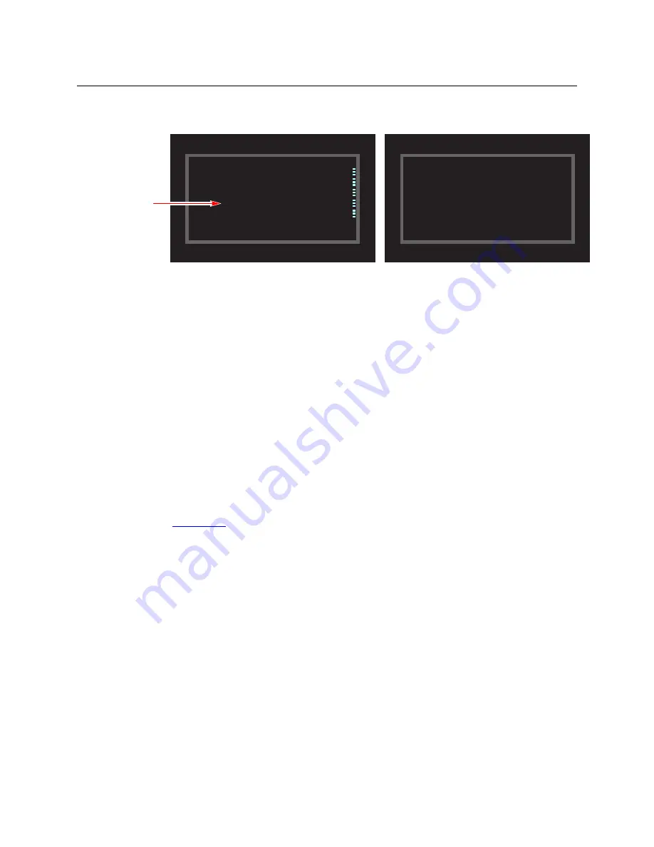
4 At this point, the level mapping is complete. The display shows a plus sign next to the level
indicating that you can view details about the level using an ‘Information’ button:
After you view the information, press the ‘Information’ button again to return to the X-Y dis-
play.
5 Finally, press ‘Take’. After the take, the plus sign(s) migrate from the preset column to the sta-
tus column with the rest of the source data. You can view the level mapping after the take.
You can create multiple level mappings. Level mappings are typically used for AES levels.
The level map mode is cancelled when the next normal take is performed involving the selected
devices.
The default button text is “Level Map” but the button can have any legend.
Menu
The button puts the NV9640A panel in menu mode and places a small menu on the LCD
buttons, that provides access to a variety of panel options.
By pressing any of the menu buttons, you may enter data (such as panel ID) or change LCD
brightness values or you can view panel data. The LCD button text varies with context in menu
mode.
See
on page 70 for more detail.
Name Set Toggle
An ‘Name Set Toggle’ button toggles the panel between its default name set and the “system
name” set. Whichever name set you select becomes the “active” name set.
S
‘Name Set Toggle’ buttons are disabled while a category selection is in progress.
S
The panel requires that category/suffix device selection be performed using the names in
the system name set. However, it displays the device you selected using the active name set.
We recommend that you switch to the system name set prior to category/suffix device selec-
tion and return to your preferred name set afterward.
Preset
Status
Level/Dest
X Y HD
X Y HD
Dest CAM14 CAM1 SD
Dest CAM14 CAM1 SD
VTR1 CAM14 CAM1 AUDIO 1
VTR1 CAM14 CAM1 AUDIO 1
CAM14 CAM1 AUDIO 2
CAM14 CAM1 AUDIO 2
+CAM14 CAM1 AUDIO 3
+CAM14 CAM1 AUDIO 3
CAM14 CAM1 AUDIO 4
CAM14 CAM1 AUDIO 4
TIMECODE
TIMECODE
Page 1
Page 1
Preset
Status
Level/Dest
AUDIO 1 on CAM14 is preset to AUDIO 3 on
AUDIO 1 on CAM14 is preset to AUDIO 3 on
VTR1.
VTR1.
X-Y Display
Information Display
Mapping
marked
Summary of Contents for Miranda NV9640A
Page 1: ...NV9640A NV9000 Control Panel User s Guide UG0072 01 30 Apr 2013 ...
Page 6: ...vi ...
Page 56: ...46 Configuration Global Navigation ...
Page 97: ...87 NV9640A User s Guide ...
Page 98: ...88 Technical Details Drawings ...
Page 100: ...90 Misc Topics Ordering Information ...
Page 110: ...100 Index ...
Page 112: ......


