background image

Instal

la

tio

n

MACH4

002

Release

 16

 0

3/2021

61

6.5.5

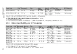
Bidirectional Gigabit Ethernet SFP transceiver

SFP-GIG-LX/LC...

MM

1310 nm

f

50/125 µm

0 dB ... 10.5 dB

0 mi ... 0.34 mi 
(0 km ... 0.55 km)

1.0 dB/km

800 MHz×km

SFP-GIG-LX/LC...

MM

1310 nm

g

62.5/125 µm 0 dB ... 10.5 dB

0 mi ... 0.34 mi 
(0 km ... 0.55 km)

1.0 dB/km

500 MHz×km

SFP-GIG-LX/LC...

SM

1310 nm 

9/125 µm

0 dB ... 10.5 dB

0 mi ... 12.43 mi 
(0 km ... 20 km)

h

0.4 dB/km

3.5 ps/(nm×km)

a. MM = Multimode, SM = Singlemode, LH = Singlemode Longhaul

b. Including 3 dB system reserve when compliance with the fiber data is observed.

c. With F/O adapter compliant with IEEE 802.3-2002 Clause 38 (single-mode fiber offset-launch mode conditioning patch cord).

d. With F/O adapter compliant with IEEE 802.3-2002 Clause 38 (single-mode fiber offset-launch mode conditioning patch cord).

e. Including 2.5 dB system reserve when compliance with the fiber data is observed.

f.

With F/O adapter compliant with IEEE 802.3-2002 Clause 38 (single-mode fiber offset-launch mode conditioning patch cord).

g. With F/O adapter compliant with IEEE 802.3-2002 Clause 38 (single-mode fiber offset-launch mode conditioning patch cord).

h. Including 2.5 dB system reserve when compliance with the fiber data is observed.

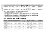
Product code

Mode

a

Wave length 
TX

Wave length 
RX

Fiber

System 
attenuation

Example for F/O line 
length

b

Fiber 
attenuation

BLP/Dispersion

M-SFP-BIDI Type 
A LX/LC EEC

SM

1310 nm

1550 nm

9/125 µm

0 dB ... 11 dB

0 km ... 12.43 mi 
(0 km ... 20 km)

0.4 dB/km

3.5 ps/(nm×km)

M-SFP-BIDI Type 
B LX/LC EEC

SM

1550 nm

1310 nm

9/125 µm

0 dB ... 11 dB

0 km ... 12.43 mi 
(0 km ... 20 km)

0.25 dB/km

19 ps/(nm×km)

M-SFP-BIDI Type 
A LH/LC EEC

LH

1490 nm

1590 nm

9/125 µm

5 dB ... 24 dB

14.29 mi ... 49.71 mi 
(23 km ... 80 km) 

0.25 dB/km

19 ps/(nm×km)

M-SFP-BIDI Type 
B LH/LC EEC

LH

1590 nm

1490 nm

9/125 µm

5 dB ... 24 dB

14.29 mi ... 49.71 mi 
(23 km ... 80 km) 

0.25 dB/km

19 ps/(nm×km)

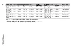
SFP-GIG-BA LX/
LC EEC

SM

1310 nm

1550 nm

9/125 µm

0 dB ... 15 dB

0 km ... 12.43 mi 
(0 km ... 20 km)

0.4 dB/km

3.5 ps/(nm×km)

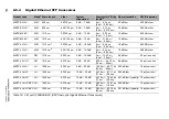
Table 17: F/O port (bidirectional Gigabit Ethernet SFP transceiver)

Product code

Mode

a

Wave length

Fiber

System 
attenuation

Example for F/O line 
length

b

Fiber attenuation

BLP/Dispersion

Table 16: F/O port 1000BASE-FX (SFP fiber optic Gigabit Ethernet Transceiver)

Summary of Contents for Hirschmann MACH4002 Series

Page 1: ...B V 24 6 1 6 2 6 3 6 4 6 5 6 6 6 7 6 8 6 9 6 10 6 11 6 12 6 13 6 14 6 15 6 16 SELECT LED MACH 4002 48 4G FAULT RL2 LS DA 6 1 6 16 LS DA RL1 LS DA M4 FAST 8TP RJ45 PoE M4 FAST 8SFP MACH4002 48G 6 1 6 2 6 3 6 4 6 5 6 6 6 7 6 8 P 1 LS DA 2 3 4 5 6 7 8 M4 8TP RJ45 LS DA LS DA LS DA LS DA LS DA LS DA LS DA R 1 LS DA 2 3 4 5 6 7 8 LS DA LS DA LS DA LS DA LS DA LS DA LS DA P 1 LS DA 2 3 4 5 6 7 8 1 4 7 2...

Page 2: ...he performance features described here are binding only if they have been expressly agreed when the contract was made This document was produced by Hirschmann Automation and Control GmbH according to the best of the company s knowledge Hirschmann reserves the right to change the contents of this document without prior notice Hirschmann can give no guarantee in respect of the correctness or accurac...

Page 3: ... Fan 23 1 4 1 M4 AIR plug in fan 23 1 4 2 Monitoring temperature and fan 24 1 5 Integrated basic board 25 1 5 1 Left area of basic board 26 1 5 2 Right area of basic board 27 1 6 Signal contact 28 1 7 Media modules 28 1 7 1 M4 8TP RJ45 29 1 7 2 M4 FAST 8 SFP 29 1 7 3 M4 GIGA 8 SFP 29 1 8 SFP XFP transceiver 30 1 9 Ethernet ports 31 1 9 1 10 100 1000 Mbit s twisted pair port 31 1 9 2 100 Mbit s F O...

Page 4: ... chassis connecting with the MACH4002 device 43 2 5 Installing the M4 AIR plug in fan unit 44 2 6 Installing the plug in power units in the M4 POWER power unit chassis 45 2 7 Installing media modules 45 2 8 Installing an SFP transceiver optional 47 2 9 Connecting the supply voltage 47 2 10 Wiring and installing the signal contact 49 2 11 Connecting data cables 50 3 Making basic settings 51 4 Maint...

Page 5: ...ectional Fast Ethernet SFP transceiver 59 6 5 4 Gigabit Ethernet SFP transceiver 60 6 5 5 Bidirectional Gigabit Ethernet SFP transceiver 61 6 6 Power consumption power output 63 6 7 Scope of delivery 64 6 7 1 MACH4002 64 6 7 2 M4 POWER 64 6 7 3 M4 S 64 6 7 4 M4 P 64 6 8 Order numbers product description 65 6 9 Accessories 66 6 10 Underlying technical standards 69 A Further support 70 ...

Page 6: ...s Obey all safety messages that follow this symbol to avoid possible injury or death The addition of this symbol to a Danger or Warning safety label indicates that an electrical hazard exists which will result in personal injury if the instructions are not followed This symbol points out the dangers posed by hot device surfaces In connection with safety notes the disregard of these instructions wi...

Page 7: ...cations This is the prerequisite for grounding and labeling circuits devices and systems in accordance with current standards in safety technology Qualified personnel are aware of the dangers that exist in their work Qualified personnel are familiar with appropriate measures against these hazards in order to reduce the risk for themselves and others Qualified personnel receive training on a regula...

Page 8: ...tch cabinet safely In particular check the supply voltage connections if they are not connected directly to the supply cable e g when using power strips Signal contacts FAULT Exclusively connect SELV circuits with voltage restrictions according to IEC 60950 1 or ES1 circuits according to IEC EN 62368 1 to the signal contacts Shielded ground The shielded ground wire of the twisted pairs cables is c...

Page 9: ...ever insert pointed objects narrow screwdrivers wires etc into the device or into the connection terminals for electric conductors Do not touch the connection terminals Seal all unused slots with cover panels Modules fans and power supply units of a switched on device may only be installed or removed by an electrician Fans are subject to natural wear If one or more fans in the plug in fan fail fun...

Page 10: ...tion degree that complies with the specifications in the technical data Increased ambient temperature When you are operating the device in a closed switch cabinet or together with other devices in a switch cabinet the ambient temperature in the switch cabinet can be higher than the ambient temperature in the room Only install the device in an ambient temperature in line with the maximum ambient te...

Page 11: ...magnetic compatibility In accordance with the above named EU directive s the EU conformity declaration will be at the disposal of the relevant authorities at the following address Hirschmann Automation and Control GmbH Stuttgarter Str 45 51 72654 Neckartenzlingen You find the EU conformity declaration as PDF file for downloading on the Internet at https www doc hirschmann com certificates html The...

Page 12: ... operation Note This equipment has been tested and found to comply with the limits for a Class A digital device pursuant to part 15 of the FCC Rules These limits are designed to provide reasonable protection against harmful interference when the equipment is operated in a commercial environment This equipment generates uses and can radiate radio frequency energy and if not installed and used in ac...

Page 13: ... Reference Manual Graphical User Interface Reference Manual Command Line Interface The Network Management Software Industrial HiVision provides you with options for smooth configuration and monitoring You find further information on the Hirschmann product pages on the internet www hirschmann com de Hirschmann Industrial_Ethernet Netzmanagement index phtml With the Industrial HiVision Network Manag...

Page 14: ...14 Installation MACH4002 Release 16 03 2021 Key The symbols used in this manual have the following meanings Listing Work step Subheading ...

Page 15: ...wer unit chassis with up to three hot swappable plug in power units The switches and the power unit chassis are suitable for mounting in the 19 rack The device allows you to set up switched Industrial Ethernet networks according to standard IEEE 802 3 The HIPER Ring redundancy concept enables you to quickly carry out a reconfiguration and also a simple configuration with only one additional connec...

Page 16: ...3 4 5 6 7 8 M4 8TP RJ45 LS DA LS DA LS DA LS DA LS DA LS DA LS DA R 1 LS DA 2 3 4 5 6 7 8 LS DA LS DA LS DA LS DA LS DA LS DA LS DA P 1 LS DA 2 3 4 5 6 7 8 1 4 7 2 5 8 3 6 M4 FAST 8SFP P 1 2 3 4 5 6 7 8 1 4 7 2 5 8 3 6 P P1 P2 P3 P4 RM RL1 RL2 FAN RUN L D FDX 1000 AN TP FO RING PORT STBY LED TEST 2 1 1 2 3 4 LED MEDIA SLOTS M4 AIR SLOT PORT USB V 24 6 1 6 2 6 3 6 4 6 5 6 6 6 7 6 8 6 9 6 10 6 11 6 ...

Page 17: ...MACH4002 24G P 1 LS DA 2 3 4 5 6 7 8 M4 8TP RJ45 LS DA LS DA LS DA LS DA LS DA LS DA LS DA R 1 LS DA 2 3 4 5 6 7 8 LS DA LS DA LS DA LS DA LS DA LS DA LS DA P 1 LS DA 2 3 4 5 6 7 8 1 4 7 2 5 8 3 6 M4 FAST 8SFP P 1 2 3 4 5 6 7 8 1 4 7 2 5 8 3 6 P P1 P2 P3 P4 RM RL1 RL2 FAN RUN L D FDX 1000 AN TP FO RING PORT STBY LED TEST 2 1 1 2 3 4 LED MEDIA SLOTS M4 AIR SLOT PORT USB V 24 5 1 5 2 5 3 6 1 6 2 6 3...

Page 18: ... basic devices with different ranges of functions see on page 65 Order numbers product description The software supplied defines the range of functions Software Layer 2 Professional L2P Software Layer 3 Enhanced L3E static routing Software Layer 3 Professional L3P Multicast routing Basic device Maximum number of ports on the device in brackets number of installed ports on the basic board Maximum n...

Page 19: ...Ethernet ports XFP slots for 10GBASE SR LR Media module 5 and 16 Gigabit Ethernet RJ45 ports 10 100 1000BASE TX Media module 6 Along with the 10 Gigabit if present Gigabit and Fast Ethernet ports the front of the basic board also has the following connections A USB socket for connecting an AutoConfiguration Adapter ACA22 A V 24 socket for the network management connection 2 signal contacts that ar...

Page 20: ...al 2 M4 POWER connection voltage input P4 1 P4 2 external 3 Slot for slide in power supply unit voltage input P1 and if required P2 With redundant supply the power supply unit with the higher output voltage supplies the device on its own The supply voltage is electrically isolated from the housing With non redundant supply of the mains voltage the device reports a power failure You can avoid this ...

Page 21: ...e power unit chassis See Mounting the power unit chassis connecting with the MACH4002 device on page 43 The M4 POWER power unit chassis enables redundant power supply It has three slots for plug in power units The plug in power units can be replaced during operation hot swappable Depending on the plug in power units connected you can use an M4 POWER power unit chassis to implement the redundant po...

Page 22: ...ease 16 03 2021 Figure 2 M4 POWER power unit chassis front side of the device mounting with up to 3 power units 1 Power unit 1 2 Power unit 2 3 Power unit 3 Figure 3 M4 POWER power unit chassis back side of the device 1 2 3 1 2 3 ...

Page 23: ...ans as described in the following On the front side of the MACH4002 basic device the fan plug in unit M4 AIR is located on the left You can replace the plug in fan during operation See Installing the M4 AIR plug in fan unit on page 44 See Deinstalling the M4 AIR plug in fan unit on page 54 M4 AIR Fan plug in unit for switch basic device MACH4002 without temperature sensor for the use in ambient ai...

Page 24: ...MTBF value or triggers error statuses and it usually leads to transmission errors on the Ethernet connections Temperature difference The difference between the ambient temperature and the circuit board PCB temperature is primarily independent of the ambient temperature MACH4002 device Temperature difference Ambient to PCB with all fans at full speed Temperature difference Ambient to PCB with all f...

Page 25: ...7 Basic board MACH4002 24G 3X Figure 8 Basic board MACH4002 48G 3X MACH4002 device Printed circuit board PCB temperature threshold value MACH4002 48 4G Ambient temperature 20 K MACH4002 24G 48G Ambient temperature 27 K Table 8 Temperature monitoring USB V 24 6 1 6 2 6 3 6 4 6 5 6 6 6 7 6 8 SELECT LED MACH 4002 24G FAULT RL2 LS DA 6 1 RL1 6 1 6 2 6 3 6 4 6 5 6 6 6 7 6 8 USB V 24 6 1 6 2 6 3 6 4 6 5...

Page 26: ...alternatives to RJ45 ports 6 1 6 8 See Ethernet ports on page 31 Three 10 Gigabit Ethernet ports XFP in MACH4002 24G 3X and MACH4002 48G 3X There are 3 10 Gigabit Ethernet ports port number 5 1 5 3 for connecting network segments on the left side of the basic board These ports are XFP slots The following 10 Gigabit Ethernet XFP transceivers are available to you for the MACH4002 3X M XFP SR LC M XF...

Page 27: ...as alternatives to the SFP ports 6 1 6 8 on the left side of the basic board combo ports 8 Gigabit Ethernet ports in MACH4002 24G and MACH4002 24G 3X There are 8 10 100 1000BASE TX ports port number 6 1 6 8 for connecting network segments on the right side of the basic board These ports are RJ45 sockets In the MACH4002 24G the RJ45 ports 6 1 6 8 can be used as alternatives to the SFP ports 6 1 6 8...

Page 28: ...so use the management to switch the signal contact manually and thus control external devices 1 7 Media modules Figure 10 Fast Ethernet media modules and Gigabit Ethernet media modules MACH4002 device M4 8TP RJ45 M4 FAST 8 SFP M4 GIGA 8 SFP MACH4002 24G 0 2 Media modules 0 2 Media modules 0 2 Media modules MACH4002 48G 0 4 Media modules 0 4 Media modules 0 4 Media modules Table 9 Possible media mo...

Page 29: ... available to you for the M4 FAST 8 SFP media module Fast Ethernet SFP transceivers M FAST SFP MM LC M FAST SFP SM LC M FAST SFP SM LC M FAST SFP SM LC M FAST SFP LH LC See Ethernet ports on page 31 1 7 3 M4 GIGA 8 SFP The M4 GIGA 8 SFP media module has 8 100 1000BASE FX ports SFP slots for mounting SFP transceivers The following SFP transceivers are available to you for the M4 GIGA 8 SFP media mo...

Page 30: ...ceiver 2 Gigabit Ethernet F O SFP transceiver 3 10 Gigabit Ethernet F O XFP transceiver SFP is the acronym for Small Form factor Pluggable which is also commonly known as mini GBIC GigaBit Interface Converter Both Fast Ethernet SFP transceivers and Gigabit Ethernet SFP transceivers are available for your device XFP transceivers are slightly larger than SFP transceivers They support 10 Gigabit Ethe...

Page 31: ...Mbit s full duplex mode 10 Mbit s half duplex mode 10 Mbit s full duplex mode Delivery state Autonegotiation activated The port casing is electrically connected to the front panel The pin assignment corresponds to MDI X 1 9 2 100 Mbit s F O port This port is an SFP slot The 100 Mbit s F O port allows you to connect network components according to the IEEE 802 3 100BASE FX standard This port suppor...

Page 32: ...duplex mode Default setting Full duplex Note Make sure that you connect SR ports exclusively with SR ports LR ports exclusively with LR ports ER ports exclusively with ER ports and ZR ports exclusively with ZR ports 1 9 5 Combo ports You have the option of alternatively connecting a twisted pair cable via a RJ45 socket or an optical fiber via a SFP transceiver to a combo port By inserting a SFP tr...

Page 33: ... power unit green lights up Supply voltage 1 is present at the plug in power unit green flashing Supply voltage 1 is present but the plug in power unit is reporting an error LED Display Color Activity Meaning P2 Supply voltage none No supply voltage 2 or voltage too low at the plug in power unit green lights up Supply voltage 2 is present at the plug in power unit green flashing Supply voltage 2 i...

Page 34: ...1 none Signal contact 1 is closed it is not reporting an error or it was closed via the Manual setting yellow lights up Signal contact 1 is open The Manual setting is active red lights up Signal contact 1 is open it is reporting an error LED Display Color Activity Meaning RL2 Signal contact Relay 2 none Signal contact 2 is closed it is not reporting an error or it was closed via the Manual setting...

Page 35: ...mission speed LED Display Color Activity Meaning ON Autonegotia tion green lights up The port LEDs of the media modules display the port configuration type LED Display Color Activity Meaning RING PORT Ring port green lights up The port LEDs of the media modules display the HIPER Ring assignment LED Display Color Activity Meaning STBY Stand by green lights up The port LEDs of the media modules disp...

Page 36: ... memory operation green flashes synchronously 2 per period Saves a configuration file from the storage medium ACA to the device green flashes synchronously 1 per period Saves a configuration file from the device to the storage medium ACA LED Display Color Activity Meaning 1 n Link status none Device detects an invalid or missing link green lights up Device detects a valid link green flashes 1 time...

Page 37: ...e port LEDs of the media modules display the twisted pair ports yellow lights up Fiber optic has been selected The port LEDs of the media modules display the F O ports LED Display Color Activity Meaning 1 n RING PORT green lights up This port is assigned to the HIPER Ring LED Display Color Activity Meaning 1 n Stand by green lights up Connection port for the data line yellow lights up Connection p...

Page 38: ...lectrically insulated from the supply voltage Figure 13 Pin assignment of the V 24 interface and the DB9 plug You will find the order number for the terminal cable which is ordered separately in the Technical Data section see on page 55 Technical data 1 11 2 USB interface The USB interface allows you to connect the AutoConfiguration Adapter ACA22 storage medium This is used for saving loading the ...

Page 39: ... an SFP transceiver optional Connecting the supply voltage Wiring and installing the signal contact Connecting data cables Note Note the safety instructions in General safety instructions on page 7 2 1 Checking the package contents Check whether the package includes all items named in the section Scope of delivery on page 64 Check the individual parts for transport damage 2 2 Installing the device...

Page 40: ...n a flat surface such as a table stick the supplied casing feet onto the bottom of the device with approx 0 8 in 2 cm of space from the corners If necessary remove any dirt from the bottom of the device where you want to place the stick on feet Remove the protective foil from the adhesive surface of a casing foot and attach the casing foot on the device 2 2 3 Mounting in a switch cabinet The devic...

Page 41: ... rail 3 19 switching cabinet On delivery 2 mounting brackets are mounted to the sides of the device see figure below Fasten the device in the switch cabinet by screwing it in with the mounting brackets 1 3 2 P 1 LS DA 2 3 4 5 6 7 8 M4 8TP RJ45 LS DA LS DA LS DA LS DA LS DA LS DA LS DA R 1 LS DA 2 3 4 5 6 7 8 LS DA LS DA LS DA LS DA LS DA LS DA LS DA P 1 LS DA 2 3 4 5 6 7 8 1 4 7 2 5 8 3 6 M4 FAST ...

Page 42: ...perated with external DC voltage via the M4 POWER connections the device is grounded via the M4 POWER connection 2 3 Mounting the power supply unit on the back of the MACH4002 device Remove the cover panel Slide the power supply unit all the way into the basic device along the mounting rails above and below Make sure that there is a good connection between the multiple plug of the plug in power un...

Page 43: ...te the external power supply from the M4 POWER power unit chassis Remove all the plug in power units from the M4 POWER power unit chassis Connect one end of the M4 POWER CABLE to the MACH4002 device Connect the other end of the M4 POWER CABLE to the M4 POWER power unit chassis Connect the MACH4000 device and the M4 POWER power unit chassis with the mounting bracket included in the delivery Slot al...

Page 44: ...ug in power units 1 Plug in power unit 1 2 Plug in power unit 2 3 Not used 4 M4 POWER power unit chassis front of device 2 5 Installing the M4 AIR plug in fan unit Slide the new plug in fan unit all the way into the basic device along the mounting rails above and below Make sure that there is a good connection between the multiple plug of the plug in fan unit and the female multipoint of the syste...

Page 45: ... and the female multipoint of the system bus Screw the slotted head screws in the front panel of the plug in power unit flush with the frame of the basic device Connect the power supply cables Note The tightening torque 0 79 Nm 7 lb in for input connections 1 24 Nm 11 lb in for input connections 2 7 Installing media modules The switch has 4 inputs for connecting media modules The number of connect...

Page 46: ...e cover panel from the media module slot on the basic device Note the positions of the blue insertion catches see the figure above step 1 Insert the media module almost as far as it will go into the desired slot see figure above step 2 Make sure that there is a good connection between the multiple plugs of the media module and the female multipoints of the system bus Insert the media module as far...

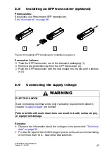
Page 47: ...r 2 Push the SFP transceiver with the lock closed into the slot until it latches in 3 2 9 Connecting the supply voltage Remarks Observe the information about the voltages to be connected Technical data on page 55 For the AC input of the AC DC plug in power units use a nominal rating of not more than 16 A slow blow characteristic WARNING ELECTRIC SHOCK Start connecting electrical wires only if all ...

Page 48: ...ross section of at least 2 5 mm North America AWG12 For the current conductors at the voltage input of the AC DC plug in power units use a cable cross section of at least 1 0 mm North America AWG16 Connect the power supply cable to the power input Install strain relief Switch on the plug in power units to start up the device WARNING This applies exclusively to device variants with a DC power suppl...

Page 49: ...tandby mode Control cable interrupted Control cable short circuited Partner device is in standby mode The following conditions are reported in normal mode Control cable short circuited Partner device is in normal mode The following condition is also reported in RM mode Ring redundancy reserve is available On delivery there is no ring redundancy monitoring Pull the terminal block off the device and...

Page 50: ...e data transmission between the buildings When using copper cables provide a sufficient separation between the power supply cables and the data cables Ideally install the cables in separate cable channels Verify that power supply cables and data cables do not run parallel over longer distances To reduce inductive coupling verify that the power supply cables and data cables cross at a 90 angle Use ...

Page 51: ... address The device looks for the IP address using DHCP Password for management Login user password public read only Login admin password private read and write V 24 data rate 9600 Baud Ring redundancy disabled Ethernet ports link status is not evaluated signal contact Optical 100 Mbit s ports 100 Mbit s full duplex Optical 10 Gbit s ports 10 Gbit s full duplex All other ports autonegotiation Ring...

Page 52: ...acts and the switching function depending on the frequency of the switching operations Hirschmann is continually working on improving and developing their software Check regularly whether there is an updated version of the software that provides you with additional benefits You find information and software downloads on the Hirschmann product pages on the Internet http www hirschmann com Depending...

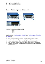
Page 53: ...age 8 and General safety instructions on page 7 ff Lever the selected media module from the slot by pulling the blue insertion catches see figure above steps 1 and 2 Pull the media module out of the slot see figure above step 3 Close the media module slot on the basic device using a cover panel Screw the four knurled screws in the cover panel flush with the frame of the basic device 2 1 3 ...

Page 54: ...he SFP transceiver with the protection cap 3 5 3 Deinstalling the M4 AIR plug in fan unit Remove the 2 screws in the front panel of the M4 AIR plug in fan unit Pull the plug in fan unit out a few centimeters and wait until the fan comes to a halt before pulling it all the way out CAUTION ROTATING PARTS After the device is switched off the fan blades continue rotating for a number of seconds Do not...

Page 55: ...00W typ 40 0 A at 265 V AC and cold start typ 40 0 A at 265 V AC and cold start Overload current protection at input Non replaceable fuse Potentialdifference between input voltage and casing M4 VDC 300W Potential difference from input voltage 24 V DC 48 V DC 60 V DC Potential difference from input voltage 0 V 60 V DCa Signal contact FAULT Switching current Switching voltage Insulation voltage max ...

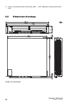
Page 56: ...elease 16 03 2021 6 2 Dimension drawings Figure 22 Dimensions a The 0 V connections within a DC module M4 VDC 300W are connected with each other mm inch 482 6 19 00 465 1 18 31 76 2 3 00 4 6 0 18 430 5 16 95 15 3 0 60 445 17 52 ...

Page 57: ...transients burst Power line Data line 2 kV 4 kV IEC EN 61000 4 5 Voltage surges Power line line line Power line line earth Data line 2 kV 2 kV 4 kV IEC EN 61000 4 6 Line conducted interference voltages 150 kHz 80 MHz 10 V EN 61000 4 9 Pulse magnetic fields 300 A m EMC interference emission EN 55032 Class A Yes FCC 47 CFR Part 15 Class A Yes German Lloyd Classification Construction Guidelines VI 7 ...

Page 58: ...10 nm 62 5 125 µm 0 dB 11 dB 0 mi 2 49 mi 0 km 4 km 1 0 dB km 500 MHz km M FAST SFP SM LC SM 1310 nm 9 125 µm 0 dB 13 dB 0 mi 15 53 mi 0 km 25 km 0 4 dB km 3 5 ps nm km M FAST SFP SM LC SM 1310 nm 9 125 µm 10 dB 29 dB 15 53 mi 40 39 mi 25 km 65 km 0 4 dB km 3 5 ps nm km M FAST SFP LH LC SM 1550 nm 9 125 µm 10 dB 29 dB 29 20 mi 64 62 mi 47 km 104 km 0 25 dB km 19 ps nm km M FAST SFP LH LC SM 1550 n...

Page 59: ... data is observed Fiber attenuation BLP Dispersion SFP FAST BA MM LC EEC MM 1310 nm 1550 nm 50 125 µm 62 5 125 µm 0 dB 16 dB 0 mi 1 24 mi 0 km 2 km 1 0 dB km 800 MHz km 500 MHz km SFP FAST BB MM LC EEC MM 1550 nm 1310 nm 50 125 µm 62 5 125 µm 0 dB 16 dB 0 mi 1 24 mi 0 km 2 km 1 0 dB km 800 MHz km 500 MHz km SFP FAST BA SM LC EEC SM 1310 nm 1550 nm 9 125 µm 0 dB 18 dB 0 km 12 43 mi 0 km 20 km 0 4 d...

Page 60: ...LX LC MM 1310 nmd 62 5 125 µm 0 dB 10 5 dB 0 mi 0 34 mi 0 km 0 55 km 1 0 dB km 500 MHz km M SFP LX LC SM 1310 nm 9 125 µm 0 dB 10 5 dB 0 mi 12 43 mi 0 km 20 km e 0 4 dB km 3 5 ps nm km M SFP LX LC SM 1310 nm 9 125 µm 5 dB 20 dB 8 70 mi 26 10 mi 14 km 42 km 0 4 dB km 3 5 ps nm km M SFP LH LC LH 1550 nm 9 125 µm 5 dB 22 dB 14 29 mi 49 71 mi 23 km 80 km 0 25 dB km 19 ps nm km M SFP LH LC LH 1550 nm 9...

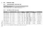
Page 61: ...ith F O adapter compliant with IEEE 802 3 2002 Clause 38 single mode fiber offset launch mode conditioning patch cord h Including 2 5 dB system reserve when compliance with the fiber data is observed Product code Modea Wavelength TX Wave length RX Fiber System attenuation Example for F O line lengthb Fiber attenuation BLP Dispersion M SFP BIDI Type A LX LC EEC SM 1310 nm 1550 nm 9 125 µm 0 dB 11 d...

Page 62: ... ps nm km SFP GIG BA LH LC EEC LH 1490 nm 1550 nm 9 125 µm 4 dB 24 dB 11 80 mi 49 71 mi 19 km 80 km 0 25 dB km 19 ps nm km SFP GIG BB LH LC EEC LH 1550 nm 1490 nm 9 125 µm 4 dB 24 dB 11 80 mi 49 71 mi 19 km 80 km 0 25 dB km 19 ps nm km a MM Multimode SM Singlemode LH Singlemode Longhaul b Including 3 dB system reserve when compliance with the fiber data is observed Product code Modea Wavelength TX...

Page 63: ... LC M SFP LH LC M SFP LX LC M SFP LX LC M SFP MX LC M SFP SX LC 1 0 W 1 0 W 1 0 W 1 0 W 1 0 W 1 0 W 3 4 Btu IT h 3 4 Btu IT h 3 4 Btu IT h 3 4 Btu IT h 3 4 Btu IT h 3 4 Btu IT h M FAST SFP MM LC M FAST SFP SM LC M FAST SFP SM LC M FAST SFP LH LC 1 0 W 1 0 W 1 0 W 1 0 W 3 4 Btu IT h 3 4 Btu IT h 3 4 Btu IT h 3 4 Btu IT h M XFP SR LC M XFP LR LC M XFP ER LC M XFP ZR LC 3 0 W 3 0 W 3 0 W 3 0 W 10 2 B...

Page 64: ...1 Safety and general information sheet 2 Brackets with fastening screws pre mounted Amount Article 1 Power supply plug in unit for switch basic device M4 S 300W 1 Safety and general information sheet Depending on device variant Cable for AC connection for AC supply Amount Article 1 Power supply plug in unit for switch basic device M4 S 300W 1 Safety and general information sheet Depending on devic...

Page 65: ...H4002 24G 3X L2P MACH4002 24G 3X L3E MACH4002 24G 3X L3P Switch basic device 24G 3X up to 24 Gigabit Ethernet ports and 3 10 Gigabit Ethernet ports including fan plug in unit without power supply unit with Software Layer2 Professional with Software Layer3 Enhanced with Software Layer3 Professional 943 915 101 943 915 201 943 915 301 MACH4002 48G 3X L2P MACH4002 48G 3X L3E MACH4002 48G 3X L3P Switc...

Page 66: ... applicable for combo ports Not applicable for ports which support only Gigabit Ethernet It is currently not possible to set autocrossing manually M FAST SFP MM LC 943 865 001 M FAST SFP MM LC EEC 943 945 001 M FAST SFP SM LC 943 866 001 M FAST SFP SM LC EEC 943 946 001 M FAST SFP SM LC 943 867 001 M FAST SFP SM LC EEC 943 947 001 M FAST SFP LH LC 943 868 001 M FAST SFP LH LC EEC 943 948 001 SFP F...

Page 67: ...FP BIDI Type A LH LC EEC 943 975 001 M SFP BIDI Type B LH LC EEC 943 975 002 M SFP BIDI Bundle LX LC EEC Type A B 943 974 101 M SFP BIDI Bundle LH LC EEC Type A B 943 975 101 SFP GIG BA LX LC EECa a You will find further information on certifications on the Internet on the Hirschmann product pages www hirschmann com 942 207 001 SFP GIG BB LX LC EECa 942 207 002 SFP GIG BA LX LC EECa 942 208 001 SF...

Page 68: ...M XFP SR LC 0 C 60 C 943 917 001 M XFP LR LC 0 C 60 C 943 919 001 M XFP ER LC 0 C 60 C 943 920 001 M XFP ZR LC 0 C 60 C 943 921 001 Other accessories Order number AutoConfiguration Adapter ACA22 USB EEC 942 124 001 Terminal cable 943 301 001 M4 POWER CABLE connection cable for redundant power supply 943 922 001 M4 RACKMOUNT mounting bracket for mounting the MACH4002 in the 19 cabinet 943 951 101 M...

Page 69: ...ric standards Immunity for industrial environments EN 55032 Electromagnetic compatibility of multimedia equipment Emission Requirements IEC EN 62368 1 Equipment for audio video information and communication technology Part 1 safety requirements EN 61131 2 Programmable controllers Part 2 Equipment requirements and tests EN 50121 4 Railway applications EMC emitted interference and interference immun...

Page 70: ...etitors on three counts with its complete range of innovative services Consulting incorporates comprehensive technical advice from system evaluation through network planning to project planning Training offers you an introduction to the basics product briefing and user training with certification You find the training courses on technology and products currently available at https www belden com s...

Page 71: ...Installation MACH4002 Release 16 03 2021 71 ...

Page 72: ......

Reviews: