132
System Configuration
Viewing a Multiviewer’s Status Information
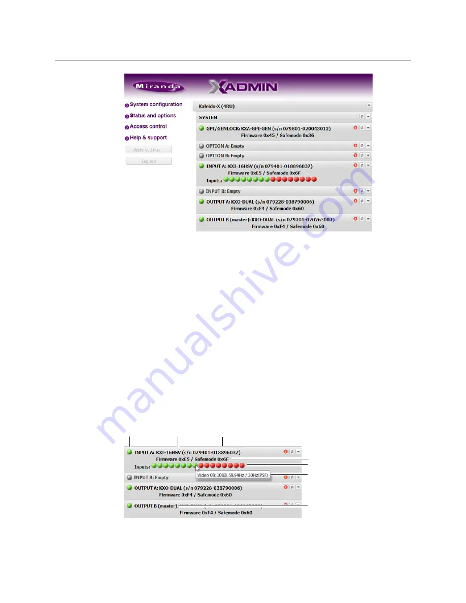
Status and Options page for a Kaleido-X 4RU
• In the case of a
Kaleido-X (7RU)
or
Kaleido-X (14RU),
cards are presented in the
order they appear, from left to right when looking at the front of the chassis.
• In the case of a
Kaleido-X (4RU),
cards are presented in the order they appear,
starting from the top left corner down, and again from the top right corner, when
looking at the front of the chassis.
• Some heading rows may show a card type, serial number, firmware and safe mode
versions, a module status indicator, and input signal status indicators.
• You can identify which output card currently assumes the
software master
role (and
is thus assigned the multiviewer’s IP address) by looking for the word “master” next
to the card’s identifier, for example: “OUTPUT A (master)”. This is shown in the figure
below.
• The module status indicator shows whether the card (or module) is running
normally (green) or in safe mode (red).
• The signal status indicators reveals the presence of a valid input signal at the
corresponding connector.
2 Move the pointer to an input signal status indicator to view the associated signal
format.
Card type Serial number
Version information
Input signal status
Input signal format
Status indicator
This card is currently the
software master
Summary of Contents for Grass Valley Kaleido-X
Page 22: ...22 Overview Functional Block Diagrams Simplified Signal Flow Diagram KX0 24Router...
Page 40: ...40 Installation Ventilation...
Page 100: ...100 IP Network Setup Network Considerations for a Multiviewer Cluster...
Page 123: ...123 Kaleido X 7RU Installation Service Manual 9 Click Finish A security warning appears...
Page 152: ...152 System Configuration Enabling Options...
Page 190: ...190 Maintenance Troubleshooting Disposal and Recycling Information...
Page 215: ...215 Kaleido X 7RU Installation Service Manual...


