background image

Installation and operating manual 

EN 

74 METPOINT

®

 BDL compact

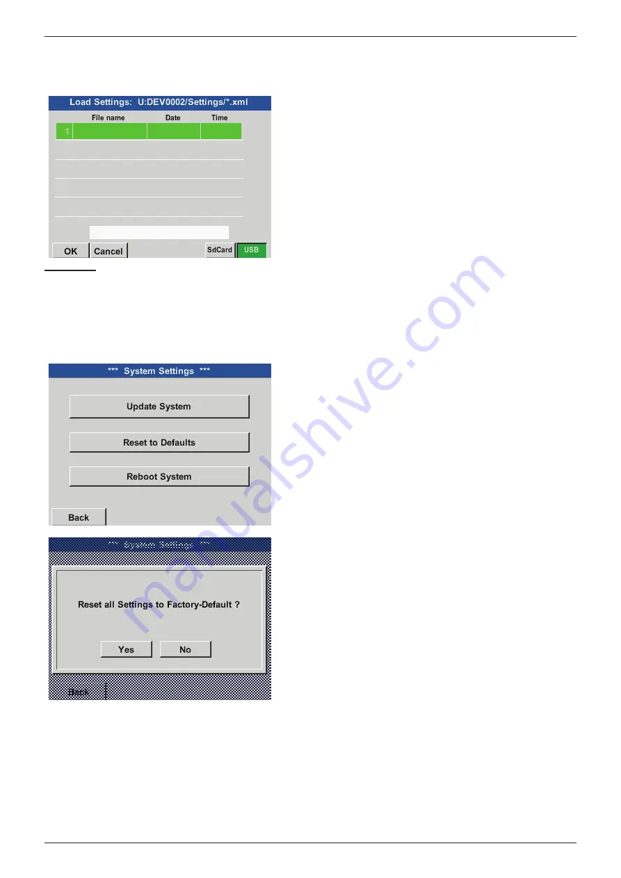
11.2.3.7.4.  Loading device settings

Home 

 Export/Import 

 Import Settings

After selecting the storage medium (SdCard or USB), 
a desired previously saved device setting can be 
selected and loaded.

Important:

After the channel and system settings have been reset, press the 

OK

 button and then press the 

Restart

 button to 

restart the BDL.

11.2.3.7.5.  Restoring factory settings

Home 

 Settings

 Device settings

 System 

Reset to Defaults

Press the key 

Reset to Defaults

 setting causes a reset 

to the factory settings.

Summary of Contents for METPOINT BDL compact

Page 1: ...METPOINT BDL compact EN english 10 089 Intelligent screen saver Installation and operating manual ...

Page 2: ...solated pulse option 19 9 4 Terminal assignment connector E RS485 Modbus 20 9 5 Terminal assignment connector A B alarm relay 20 9 6 Connection of BEKO sensors 22 9 6 1 Connection of METPOINT SD11 SD21 22 9 6 1 1 Analogue 2 wire 4 20 mA 22 9 6 2 Connection of METPOINT SD23 23 9 6 2 1 Analogue 4 wire 4 20 mA 23 9 6 2 2 Analogue 4 wire 0 10 V 24 9 6 2 3 Digital bidirectional RS485 bus system 24 9 6 ...

Page 3: ...4 20 mA 39 9 8 1 3 Analogue 4 wire 0 4 20 mA 40 9 8 2 Digital SDI interface 40 9 8 2 1 Digital 3 wire SDI interface 40 9 8 2 2 Digital 4 wire SDI interface 41 9 8 3 Digital bidirectional RS485 bus system 41 10 Connecting the METPOINT BDL compact with a PC 42 11 Operation of METPOINT BDL compact 43 11 1 Home Main Menu 43 11 1 1 Initialisation 43 11 1 2 Home after switching on 44 11 2 Settings 44 11...

Page 4: ...on 86 11 2 8 2 Selecting sensor type 87 11 3 Web server optional 88 11 3 1 Activating web server option 88 11 3 2 User interface 89 11 3 2 1 Information 89 11 3 2 2 Selecting language 90 11 3 3 Login 90 11 3 4 Favourites 91 11 3 5 Status 91 11 3 6 Current value 92 11 3 7 Display 93 11 3 8 Chart 94 11 3 9 AlarmMail 95 11 3 10 User 96 11 3 11 EMail 96 11 4 Data logger settings 97 11 5 Charts 101 11 ...

Page 5: ...rding to ISO 3864 and ANSI Z 535 DANGER Imminent danger Consequences of non compliance serious or even fatal injury WARNING Potential danger Consequences of non compliance serious or even fatal injury CAUTION Imminent danger Consequences of non compliance injury and or damage to property NOTICE Potential danger Consequences of non compliance injury and or damage to property IMPORTANT Additional no...

Page 6: ...roperty All tasks described in this operating manual must be performed by skilled technical personnel who meet the criteria outlined below CAUTION Malfunction of BDL compact Incorrect installation or insufficient maintenance can result in malfunction of the BDL so that the incorrect values are displayed DANGER Inadmissible operating parameters If the specified limits are exceeded there is a risk o...

Page 7: ...tions for measurements are two of the main advantages of the BDL over conventional paperless screen recorders Alarm output 4 20 mA output 4 20 mA sensors third party providers RS 485 Modbus RTU sensors third party providers Electric meter third party providers Pulse sensors third party providers RS 485 Modbus 0 1 V 10 V third party providers Volume flow sensor e g FS 211 Volume flow sensor e g FS ...

Page 8: ...e technical data specified in data sheet are binding Improper handling or operation of the device outside the technical specifications is not permissible Claims for compensation for damage caused by improper use are excluded 4 Type plate The type plate is attached to the device housing It contains all relevant technical data of the METPOINT BDL compact data logger Please have these details to hand...

Page 9: ...nts CAUTION Risks from damaged components If you suspect that the METPOINT BDL compact is damaged do not start it Defective components might impair the operational safety of the METPOINT BDL compact or result in incorrect measurements and lead to serious damage The METPOINT BDL compact must be stored in the original packaging Seal the packaging and store it in a dry and frost free room Ensure that...

Page 10: ...ion M12x1 5 Body Brass nickel plated Terminal size 3 7 mm WS 16 mm Tightening torque 8 Nm 1x RJ45 for Ethernet connection Interfaces USB memory stick USB 2 0 Ethernet interface Modbus TCP RS485 interface Modbus RTU SDI interface Serial Data Interface Sensor inputs 4 2x2 sensor inputs for analog and digital sensors free assignment Sensor signals 5 Analog signals 0 1 10 30 V Pulse signals Pt100 Pt10...

Page 11: ...Panasonic CR2032 Rated voltage 3 V Capacitance 225 mAh Max continuous current 0 2 mA Diameter 20 mm Height 3 2 mm Weight 2 9 g Operating temperature 30 60 C 5 BEKO sensors Digital BEKO sensors for pressure dew point and consumption with RS485 interface Series DPM SD23 FLM SFxx Digital BEKO sensors for dew point and consumption with SDI interface Series DP 109 DP 110 FS 109 FS 211 Analogue BEKO sen...

Page 12: ...ting Notice Wall mounting For wall mounting use fixtures that can carry at least 4 times the weight of the device 10 8 kg 2 x O6 5 0 3 140 5 5 140 5 5 180 7 1 26 1 26 1 115 4 5 166 6 5 140 5 5 32 1 3 26 1 26 1 160 6 3 44 1 7 BEKO TECHNOLOGIES BDL compact SdCard Chart Chart Real time values Channels Real time values Alarm overview Export Import Settings Software Version 3 03 Hardware Version 1 21 A...

Page 13: ... BEKO TECHNOLOGIES BDL compact Lg run Software Version 1 01 Hardware Version 1 21 Alarm 15 56 13 24 06 2014 Interval Chart Chart Real time values Channels Real time values Alarm overview Export Import Settings Cut out for control panel installation 8 x R5 4 x O 5 0 2 4 x O 5 0 2 122 4 8 122 4 8 3 4 1 3 69 2 7 8 0 3 max 109 4 3 109 4 3 in mm inch in mm inch ...

Page 14: ...e installed in the vicinity of the device The circuit breaker must conform to IEC 60947 1 and IEC 60947 3 The circuit breaker must disconnect all electrical conductors from the mains power supply The circuit breaker must not be installed in the power supply line The circuit breaker must at all times be easily accessible to operating personnel To disconnect the device from the power mains pull the ...

Page 15: ... NOTICE Insulation The additional insulation must be suitable for a test voltage of 1500 VAC The thickness of the insulation must be at least 0 4 mm e g insulating tubing type BI 85 from Bierther GmbH The additional insulation of the power cables mains connection alarm and signalling relays can be implemented as follows 1 Terminals plug type connectors 2 Flexible insulating tubing for the power ca...

Page 16: ...ve the requirements of EN 61340 5 1 Do not touch electronic components while they are powered Basic safety precautions In order not to cause damage when handling electronic devices take the necessary precautions for the prevention of electrostatic charges laid down in DIN EN 61340 5 1 IEC 63140 5 and DIN EN 100 015 These precautions prevent electronic discharge and thus protect your equipment Prev...

Page 17: ...th foreign objects Ø 1 0 mm 4 Protection against splashing water Water splashing against the housing must not cause damage to the device DANGER IP class After installation service and maintenance work you must ensure that the data logger meets again the requirements of the above protection class When performing work on the METPOINT BDL compact observe the following Use only original seals Ensure t...

Page 18: ...AWG16 AWG28 Wire cross section for sensors 0 14 1 5 mm2 AWG16 AWG28 DANGER Mains voltage Incorrect connection of the device to the power mains can lead to serious or even fatal injury and cause malfunction of the METPOINT BDL compact 9 1 Terminal assignment connector C supply voltage Input voltage range 85 264 V AC 47 63 Hz 1 Ph PE Wire cross section 0 75 2 5 mm2 AWG12 AWG24 PE L N 3 2 1 C 1 PE pr...

Page 19: ...solated pulse input pulse forwarding 9 3 1 Basic version pulse forwarding support 9 3 2 Galv isolated pulse option In systems with 2 digital boards 2x2 digital channels only 1 pulse input can be connected to a pulse output A1 or B1 for pulse 1 or A2 or B2 for pulse 2 Analog Board SDI Uv VDC Uv GND Loop Loop RS485 A RS485 B Pulse input Digital Board 1 2 3 4 5 6 7 8 PT GND 1 2 3 4 5 6 7 8 9 Uv VDC U...

Page 20: ...ower supply line ensure that the double or reinforced insulation between the electric circuits and the secondary circuit remains intact NOTICE Mains voltage The additional insulation must be suitable for a test voltage of 1500 VAC The insulation must be at least 0 4 mm thick e g insulation hose type BIS 85 from Bierther GmbH The additional insulation of the power cables mains connection alarm and ...

Page 21: ...en CAUTION Various operating states NC 1 and COM 2 are closed in the following states upon alarm upon wire break upon power failure Rating of floating alarm contacts Min switching current 10 mA Max switching voltage 250V AC 30V DC Max switching current according to VDE 3 A Contact material AgNi silver nickel C 1 2 3 1 2 3 12 34 5 678 9 12 34 5 678 12 34 5 67 12 34 5 67 1 2 3 4 5 6 7 1 2 3 4 5 6 12...

Page 22: ...D21 Pin assignment of plug type connector M12 x 1 4 pin A coded Pin assignment of connector Transmitter side Pin assignment of connector Bush side view Pin assignment of connector Screw side 4 1 3 2 4 1 3 2 4 1 3 2 9 6 1 1 Analogue 2 wire 4 20 mA Connection diagram METPOINT SD11 SD21 and METPOINT BDL compact UV I UV IOUT RL 4 20 mA 1 3 I 4 20 mA SD11 SD21 METPOINT BDL compact Analog Board 1 2 3 4 ...

Page 23: ...ue 4 wire 4 20 mA Connection diagram METPOINT SD23 and METPOINT BDL compact UV I V PT I UV UV UV IOUT GND RL 4 20 mA 1 5 4 6 SD23 I 4 20 mA METPOINT BDL compact Analog Board 1 2 3 4 5 6 7 8 9 Pin assignment sensor Function Wire colour Pin assignment BDL compact PIN 1 UV Plus connection voltage supply brown PIN 1 UV PIN 4 IOUT Current output white PIN 5 I PIN 6 GND Analogue reference potential blac...

Page 24: ...UT Voltage output white PIN 8 V PT PIN 4 not assigned PIN 6 not assigned PIN 7 not assigned PIN 8 not assigned 9 6 2 3 Digital bidirectional RS485 bus system Connection diagram METPOINT SD23 and METPOINT BDL compact 1 5 7 8 RS485 SD23 UV UV UV UV A RS485 A B RS485 B METPOINT BDL compact Digital Board 1 2 3 4 5 6 7 8 Pin assignment sensor Function Wire colour Pin assignment BDL compact PIN 1 UV Plu...

Page 25: ...ssignment of connector Screw side 4 1 3 2 4 1 3 2 4 1 3 2 9 6 3 1 Analogue 2 wire 4 20 mA Connection diagram METPOINT SP11 SP21 SP61 and METPOINT BDL compact SP11 21 61 UV I UV IOUT RL 4 20 mA 1 3 I 4 20 mA METPOINT BDL compact Analog Board 1 2 3 4 5 6 7 8 9 Pin assignment sensor Function Wire colour Pin assignment BDL compact PIN 1 UV Plus connection supply voltage brown PIN 1 UV PIN 3 IOUT Curre...

Page 26: ...9 Pin assignment sensor Function Wire colour Pin assignment BDL compact PIN 1 UV Plus connection voltage supply brown PIN 1 UV PIN 5 UV Minus connection voltage supply blue PIN 2 UV PIN 3 GND Analogue reference potential black PIN 7 V PT I PIN 2 UOUT Voltage output white PIN 8 V PT 9 6 4 2 Analogue 3 wire 0 10 V Connection diagram METPOINT SP22 SP62 and METPOINT BDL compact SP22 SP62 UV V PT UV UV...

Page 27: ...nector Bush side view Pin assignment of connector Screw side 9 6 5 1 Digital bidirectional RS485 bus system Connection by means of plug type connector A Connection diagram METPOINT SF13 SF53 and METPOINT BDL compact digital board 1 3 2 4 RS485 SF13 SF53 METPOINT BDL compact Digital Board 1 2 3 4 5 6 7 8 UV UV UV UV A RS485 A B RS485 B Pin assignment sensor Function Wire colour Pin assignment BDL c...

Page 28: ...us connection voltage supply blue PIN 2 UV PIN 5 IOUT Current output grey PIN 5 I PIN 2 not assigned white PIN 4 not assigned black 9 6 5 3 Analogue galvanically isolated pulse output Connection by means of plug type connector B Connection diagram METPOINT SF13 SF53 and METPOINT BDL compact analogue 1 5 4 3 Impuls SF13 SF53 UV UV UV UV UV UV R 4 7kΩ R METPOINT BDL compact Analog Board 1 2 3 4 5 6 ...

Page 29: ...de 4 3 2 5 1 4 1 2 3 5 4 1 2 3 5 9 6 6 1 Digital SDI interface Connection diagram METPOINT FS109 FS211 and METPOINT BDL compact UV UV SDI SDI 3 2 I 4 20 mA FS109 FS211 1 UV UV METPOINT BDL compact Digital Board 1 2 3 4 5 6 7 8 Pin assignment sensor Function Wire colour Pin assignment BDL compact PIN 3 Uv Plus connection voltage supply blue PIN 1 Uv PIN 2 Uv Minus connection voltage supply white PI...

Page 30: ...assigned X22 9 not assigned X22 3 GND Analogue reference potential blue PIN 1 I X22 4 Iout Current output brown PIN 5 Uv 9 6 7 2 Digital bidirectional RS485 bus system Connection diagram METPOINT OCV compact and METPOINT BDL compact X22 9 X22 8 RS485 OCV compact A RS485 A B RS485 B METPOINT BDL compact Digital Board 1 2 3 4 5 6 7 8 Assignment OCV compact Function Wire colour Pin assignment BDL com...

Page 31: ...nal from RS485 interface white PIN 7 A RS485 PIN 5 Bus B Inverted signal from RS485 interface black PIN 8 B RS485 PIN 6 not assigned PIN 7 not assigned PIN 8 not assigned PIN 2 not assigned PIN 3 not assigned PIN 4 not assigned 9 6 9 Connection of PT 1000 9 6 9 1 Analogue 4 wire 0 10 V Connection diagram PT 1000 and METPOINT BDL compact PT 1000 METPOINT BDL compact Analog Board 1 2 3 4 5 6 7 8 9 V...

Page 32: ...e 2 wire 0 4 20 mA UV I UV IOUT RL 4 20 mA I 0 4 20 mA METPOINT BDL compact Analog Board 1 2 3 4 5 6 7 8 9 Pin assignment sensor Function Pin assignment BDL compact UV Plus output voltage supply PIN 1 UV IOUT Current output PIN 5 I 9 7 1 2 Analogue 3 wire 0 4 20 mA Connection diagram analogue 3 wire 0 4 20 mA UV I UV UV UV IOUT RL 4 20 mA I 0 4 20 mA METPOINT BDL compact Analog Board 1 2 3 4 5 6 7...

Page 33: ...utput voltage supply PIN 1 UV UV Minus connection voltage supply PIN 2 UV IOUT Current output PIN 5 I GND Analogue reference potential PIN 7 V PT I 9 7 2 Analogue 0 1 10 30 V 9 7 2 1 Analogue 3 wire 0 1 10 30 V Connection diagram analogue 3 wire 0 1 10 30 V UV V PT UV UV UV UOUT RL 0 10 V U 0 1 10 30 V METPOINT BDL compact Analog Board 1 2 3 4 5 6 7 8 9 Pin assignment sensor Function Pin assignmen...

Page 34: ...s output voltage supply PIN 1 UV UV Minus connection voltage supply PIN 2 UV GND Analogue reference potential PIN 7 V PT I Uout Voltage output PIN 8 V PT 9 7 3 Digital SDI interface 9 7 3 1 Digital 3 wire SDI interface Connection diagram 3 wire SDI interface UV UV SDI SDI I 0 4 20 mA UV UV METPOINT BDL compact Digital Board 1 2 3 4 5 6 7 8 Pin assignment sensor Function Pin assignment BDL compact ...

Page 35: ...us connection voltage supply PIN 2 UV I OUT Current output PIN 2 UV SDI Digital interface PIN 6 SDI 9 7 4 Digital bidirectional RS485 bus system Connection diagram bidirectional RS485 bus system RS485 METPOINT BDL compact Digital Board 1 2 3 4 5 6 7 8 UV UV UV UV A RS485 A B RS485 B Pin assignment sensor Function Pin assignment BDL compact UV Plus connection voltage supply PIN 1 UV UV Minus connec...

Page 36: ...lse PIN 7 V PT I Pulse Pulse PIN 8 V PT Connection diagram pulse sensor UV UV R 4 7kΩ R METPOINT BDL cmpact Analog Board 1 2 3 4 5 6 7 8 9 V PT V PT I I 0 P on 1 2 3 t t Pin assignment sensor Function Pin assignment BDL compact Pulse Pulse PIN 7 V PT I Pulse Pulse PIN 8 V PT Connection diagram pulse sensor UV UV R 4 7kΩ R METPOINT BDL compact Analog Board 1 2 3 4 5 6 7 8 9 V PT V PT I P on t I 1 2...

Page 37: ...n assignment BDL compact Minus connection PIN 6 PT GND Minus connection PIN 7 V PT I Plus connection PIN 8 V PT Plus connection PIN 9 PT supply 9 7 6 2 3 wire resistance sensors Connection diagram 3 wire resistance sensors METPOINT BDL compact Analog Board 1 2 3 4 5 6 7 8 9 V PT PT GND PT Supply V PT I Pin assignment sensor Function Pin assignment BDL compact Minus connection PIN 6 PT GND Minus co...

Page 38: ...nection diagram 4 wire resistance sensors METPOINT BDL compact Analog Board 1 2 3 4 5 6 7 8 9 V PT PT GND PT Supply V PT I Pin assignment sensor Function Pin assignment BDL compact Minus connection PIN 6 PT GND Minus connection PIN 7 V PT I Plus connection PIN 8 V PT Plus connection PIN 9 PT supply ...

Page 39: ...nalog Board 1 2 3 4 5 6 7 8 9 I 4 20 mA SPS ZTL Pin assignment sensor Function Pin assignment BDL compact UV Plus output voltage supply PIN 1 UV IOUT Current output PIN 3 Loop Current input PLC ZTL PIN 4 Loop Current output PLC ZTL PIN 5 I 9 8 1 2 Analogue 3 wire 0 4 20 mA Connection diagram analogue 3 wire 0 4 20 mA I 4 20 mA UV I UV UV UV IOUT RL 4 20 mA I 0 4 20 mA METPOINT BDL compact Analog B...

Page 40: ... Analogue reference potential PIN 7 V PT I IOUT Current output PIN 3 Loop Current input PLC ZTL PIN 4 Loop Current output PLC ZTL PIN 5 I 9 8 2 Digital SDI interface 9 8 2 1 Digital 3 wire SDI interface Connection diagram analogue 3 wire SDI interface UV UV SDI SDI I 0 4 20 mA UV UV METPOINT BDL compact Digital Board 1 2 3 4 5 6 7 8 R 4 20 mA L I 4 20 mA SPS ZTL Pin assignment sensor Function Pin ...

Page 41: ...tput PIN 3 Loop Current input PLC ZTL PIN 4 Loop Current output PLC ZTL PIN 2 UV 9 8 3 Digital bidirectional RS485 bus system Connection diagram bidirectional RS485 bus system RS485 METPOINT BDL compact Digital Board 1 2 3 4 5 6 7 8 UV UV UV UV A RS485 Iout A B RS485 B R 4 20 mA L I 4 20 mA SPS ZTL Pin assignment sensor Function Pin assignment BDL compact UV Plus connection voltage supply PIN 1 UV...

Page 42: ...onnectors Crossover adapter After the METPOINT BDL compact has been connected to the PC you can use the METPOINT READER SW201 software for the evaluation of data in the form of charts and tables Network settings for Windows PC Windows 7 Start Control Panel Network and Sharing Center Change adapter settings LAN Connection Properties Internet Protocol Version 4 TCP IPv4 Use the following IP address ...

Page 43: ...elds The measured values are displayed as values or in the form of curves Text in green letters refers mainly to figures in the respective chapter Important menus and menu options are also shown with green letters The menu navigation is generally shown in green letters 11 1 Home Main Menu From the Home you can access all available submenus 11 1 1 Initialisation After the BDL compact has been switc...

Page 44: ...lish menu navigation Home Settings Device Settings Set Language Chapter 11 2 3 2 Date and time English menu navigation Home Settings Device Settings Date Time 11 2 Settings All settings are password protected Settings or changes must always be confirmed with OK Notice When returning to the Home and then calling up the settings menu again you must once more enter the password Home Settings Overview...

Page 45: ...aster password can be requested from BEKO TECHNOLOGIES GmbH with the serial number of the METPOINT BDL compact specified in the request 11 2 2 Sensor settings Important Sensors from BEKO TECHNOLOGIES with SDI signal such as DP109 and FS109 211 are generally pre configured and can be connected without further adjustments to a free sensor channel For instructions regarding the configuration of RS485...

Page 46: ... A D D digital channel A analog channel 11 2 2 1 Selecting sensor type example BEKO Digital sensor Home Settings Sensor settings A1 If no sensor has been configured yet No sensor is displayed in the type field Touch the No sensor text field to call up a list of sensor types see next step Home Settings Sensor settings A1 Type BEKO Digital For FS DP series sensors e g DP109 FS109 FS211 select type B...

Page 47: ...places another one enter the Counter value of the previous sensor optional Confirm with OK and go back with left arrow 1st page Important The Inside diameter should be as exact as possible as this parameter affects the accuracy of the measuring results There is general standard for inside diameter of pipes Please ask the manufacturer or measure the pipe yourself Home Settings Sensor settings A1 En...

Page 48: ...3 hPa standard cubic metre according to DIN 1343 as the reference values Do not enter the operating pressure or the operating temperature as the reference values 11 2 2 2 Labelling measurements and defining resolution decimals Note To configure the Resolution decimal places the Short name and the Value name click the Tool button Tool button Home Settings Sensor settings A1 Tool button For the Valu...

Page 49: ...e the data logger and then start it see chapter 11 2 3 Logger settings data logger 11 2 2 4 Alarm settings Home Settings Sensor settings A1 Alarm button In the alarm settings you have the option to enter Alarm 1 and Alarm 2 including the Hysteresis for each channel The alarm settings can also be configured in the Alarm overview menu accessible from Home Home Settings Sensor settings A1 Alarm butto...

Page 50: ...erent delays The set delays T1 to T4 apply to all the relays s second m minute h hour Home Settings Sensor settings A1 Alarm button Delay The set delays T1 to T4 apply to all the relays Home Settings Sensor settings A1 Alarm button Delay Delay T1 Enter the desired delay for T1 Delay T0 cannot be modified and is used for instant alarms Confirm with OK ...

Page 51: ... page Advanced settings In the Advanced settings you can determine whether the 4 20 mA analog output of the sensor is to be based on flow volume or velocity The selected field is displayed in green To set the measuring range touch the Manual scaling button Press OK to save and apply the settings Note Advanced settings are only available for Digital Press OK to save and apply the settings Notice Af...

Page 52: ...abelling and configuring text fields Enter alarm settings see chapter 11 2 2 4 Alarm settings Enter recording settings see chapter 11 2 2 3 Recording measuring data Enter the Resolution decimal places see chapter 11 2 7 5 Defining resolution decimals Home Settings Sensor settings A1 The METPOINT BDL compact recognises whether the connected sensor is a BEKO flow or a dew point sensor and automatica...

Page 53: ...set the data logger to STOP Home Settings Sensor settings A1 right arrow 2 page To enter or change a value touch a white field The Alarm see chapter 11 2 2 4 Alarm settings and Record buttons see chapter 11 2 2 3 Recording measuring data the Resolution for digital places and the Short name and the Value name see chapter 11 2 2 2 Labelling measurements and defining resolution as well as the Advance...

Page 54: ... Home Settings Sensor settings A1 right arrow 2 page Diameter Important Unless it has been automatically set enter the Inside diameter of the flow pipe In this example the Inside diameter is 27 5 mm Important The Inside diameter should be as exact as possible as this parameter affects the accuracy of the measuring results There is no general standard for inside diameter of pipes Please ask the man...

Page 55: ...s displayed with red text the respective values e g Diameter or Name have been changed Note After confirming with OK the field labels change back to black and the settings are applied Caution Reference temperature and reference pressure factory settings 20 C 1000 hPa All volume flow m h and consumption m values shown on the display refer to 20 C and 1000 hPa according to ISO 1217 Alternatively ent...

Page 56: ...labelling of the text fields see chapter 11 2 2 7 Labelling and configuring text fields 11 2 2 8 1 Type 0 4 20 mA Type 0 1 10 30 V Home Settings Sensor settings B1 Type 4 20 mA For details regarding the scaling of the sensor here type 4 20 mA corresponding to 0 25 bar refer to the data sheet of the sensor e g SP21 Home Settings Sensor settings B1 right arrow 2 page In Scal 4 mA enter the lower sca...

Page 57: ...DL compact 57 Home Settings Sensor settings B1 Unit Preselection of suitable units for 0 4 20 mA Press the Page button to page forward If required define User units user defined units Home Settings Sensor settings B2 Type 0 4 20 mA Here Type 4 20 mA ...

Page 58: ... Unit F For additional options refer to chapter 11 2 2 8 1Type 0 1 10 30 V and 0 4 20 mA 11 2 2 9 Type Pulse Home Settings Sensor settings B2 Type Normally the numerical value and the unit for 1 pulse is displayed at the sensor and can be entered in the 1 pulse field Notice In the example all text fields are already labelled and or assigned Home Settings Sensor settings B2 right arrow 2 page Pulse...

Page 59: ...Units for the current Consumption for Type Pulse Notice Here cubic metres Home Settings Sensor settings B2 right arrow 2 page Counter unit Available units for Counter unit for Type Pulse The Counter can be reset or set to a desired value at any time For additional options see chapter 11 2 2 8 1 Type 0 1 10 30 V and 0 4 20 mA ...

Page 60: ...2 9 1 Type No sensor Home Settings Sensor settings A2 Type No sensor This option is used to declare a channel that is not in use as not configured When returning from No sensor to the respective sensor settings the respective channel here channel A1 displayed as free ...

Page 61: ...an be read out Select one or more registers Va Vh and activate by checking the use box 11 2 2 10 2 General Modbus settings Home Settings Sensor settings A1 right arrow 2 page Modbus settings ID Enter the Modbus ID of the sensor available values 1 247 e g Modbus ID 12 Enter all serial transmission settings such as baud rate stop bit parity bit and timeout If the METPOINT BDL compact is connected to...

Page 62: ...ermine the numerical format and the transmission sequence of the individual numerical bytes Supported data types Data Type UI1 8b unsigned integer 0 255 I1 8b signed integer 128 127 UI2 16b unsigned integer 0 65535 I2 16b signed integer 32768 32767 UI4 32b unsigned integer 0 4294967295 I4 32b signed integer 2147483648 2147483647 R4 32b floating point number Byte order The Modbus register has a cap...

Page 63: ...A B C D HWord LWord HByte LByte HByte LByte 29235175522 AE 41 56 52 Data Order 1 Byte 2 Byte 3 byte 4 Byte A B C D AE 41 56 52 D C B A 52 56 41 AE B A D C 41 AE 52 56 C D A B 56 52 AE 41 Home Settings Sensor settings A1 right arrow 2 page Unit Touch the Unit text field to call up a list of the available units Select the unit by pressing the respective unit button Press the OK button to apply the u...

Page 64: ...act Home Settings Sensor settings A1 right arrow 2 page Scal text field Enter a factor that is applied to adjust the respective output value Home Settings Sensor settings A1 right arrow 2 page OK Press the OK button to store and apply the user defined factor ...

Page 65: ...th OK Step 3 enter a name Home Settings Sensor settings A1 Name Enter a name Step 4 define the Modbus settings Home Settings Sensor settings A1 right arrow 2 page Modbus settings Notice Further information on how to configure the text fields see chapter 11 2 2 7 Labelling and configuring text fields page 53 The Modbus ID is specified in the data sheet of the sensor here 1 Adjust the other paramete...

Page 66: ...he white buttons 1 4 The following parameters can be retrieved from the respective registers Register Designation Register address Register format Unit Scal Va Temperature 1216 HR R4 C No scal Vb Rel humidity 1152 HR R4 rH No scal Vc Dew point frost point 1536 HR R4 C td No scal Vd Dew point 1472 HR R4 C td No scal 11 2 3 Device settings Home Settings Device settings Overview of device settings ...

Page 67: ...e Home Settings Device settings Language Select the language for the METPOINT BDL compact interface 11 2 3 2 Date and time Home Settings Device settings Date time Touch the Time zone field and enter the correct UTC To cater for daylight saving time check the Daylight saving box ...

Page 68: ...in the fields Touch the IP address field An input window is displayed where the relevant entries can be made in the yellow box Touch the Host name field to enter or change the host name Enter the Subnet mask and Gateway address in the respective fields For Host name see chapter 11 2 2 7 Labelling and configuring text fields For the IP address observe the IP address classes Notice Private address r...

Page 69: ...it and parity To activate Modbus check the Enable Modbus RTU RS485 box To reset the values to the default settings press the Restore defaults button Default values Baud rate 19200 Stop bit 1 Parity even If the METPOINT BDL compact is connected to the bus terminal press the Term button to activate termination You also have the option to press the Bias button to use a BIAS To change the data format ...

Page 70: ... A1 a message is displayed If you have permitted relay reset in the Relay settings you can reset the relay by pressing the Relay 1 button Press the OK button to close the message box 11 2 3 6 SD card Home Settings Device settings SD card Reset Logger database Home Settings Device settings SD card Erase SD card To lock the currently stored data for use by the BDL compact press the Reset logger data...

Page 71: ...ngs System Overview of system settings Important Before carrying out an update save the device settings to a USB memory stick Notice The yellow field shows the update options that are available 11 2 3 7 1 System update Home Settings Device settings System System update Overview of System update functions ...

Page 72: ...ings Pressing the SdCard or USB button sets the storage medium Home Export Import Export system settings Pressing new file will initiate saving It is possible to enter a name with up to 8 characters By pressing OK the entries made are accepted and saved Saves Channel and system settings in XML format to a SdCard or USB memory stick ...

Page 73: ...tware pictures etc are shown with a green tick to the left To the right the current old and the available new versions are displayed Home Settings Device settings System System update Update selection Important If subsequent to the update the Restart button is displayed you must press it to restart the BDL Home Settings Device settings System System update Update channels Update for the BDL compac...

Page 74: ...B a desired previously saved device setting can be selected and loaded Important After the channel and system settings have been reset press the OK button and then press the Restart button to restart the BDL 11 2 3 7 5 Restoring factory settings Home Settings Device settings System Reset to Defaults Press the key Reset to Defaults setting causes a reset to the factory settings ...

Page 75: ...tion can be changed Press the Calibrate button A calibration cross appears first in the top left corner then in the bottom right corner and finally at the centre of the display Touch these crosses one after the other After calibration has been completed and the display has been properly centred on the screen confirm with OK If the display is not centred repeat the calibration process by pressing t...

Page 76: ...alue prior to dimming Notice When the display is touched again the brightness returns to 50 Subsequently the bar works like a normal slider bar Important If the Dim after box is not checked the panel remains backlit with the currently set brightness 11 2 5 Cleaning Home Settings Cleaning This function can be used to clean the touch screen while measurements are running The screen is temporarily di...

Page 77: ...nnels no HW channels for the display of calculations regarding the HW channels virtual channels and freely definable constants For each virtual channel up to 8 calculations with 3 operands and 2 operations can be configured Calculations are used to calculate Specific performance of system Total consumption of system with multiple compressors Energy costs etc For the calculation and display of the ...

Page 78: ...cting sensor type Home Settings Sensor settings Virtual channels V1 If no sensor has been configured yet No sensor is displayed in the type field Touch the type field reading No sensor to call up a list of available sensor types see next step Home Settings Sensor settings Virtual channels V1 Type If no sensor has been configured yet No sensor is displayed in the top field Pressing the Generic to s...

Page 79: ...ues must be activated separately 11 2 7 4 1 Activating virtual values Home Settings Sensor settings Virtual channels V1 right arrow 2 page V1a Use To activate a virtual value press the respective Value button e g V1a and confirm with OK 11 2 7 4 2 Defining operands Home Settings Sensor settings Virtual channels V1 right arrow 2 page 1st operand Touch the 1st operand field A list of the available h...

Page 80: ...or measurements including the defined virtual channels Press a channel button e g A1b to apply it If the Const value button has been pressed enter the value in the field using the numerical keypad Press the OK button to apply the value To correct a value press the and Clr button The button deletes the last character The Clr button deletes the entire value The procedure described here applies to al...

Page 81: ...t used button The procedure described here applies to all operators 1st operation and 2nd operation 11 2 7 4 4 Defining unit Home Settings Sensor settings Virtual channels V1 right arrow 2 page Unit for result Touch the Unit text field to call up a list of the available units Select the unit by pressing the respective unit button Press the OK button to apply the selected unit To change between the...

Page 82: ...ect an entry press the or Clr button The button deletes the last character The Clr button deletes the entire value Important After all values and operators have been entered the system is able to perform calculations with 3 values and 2 operands as follows Example V1a 1st operand 1st operation 2nd operand 2nd operation 3rd operand V1a A1c A2a 4 6 ...

Page 83: ...rts and Chart current values menus Otherwise the default designation e g V1a is displayed V1 indicates the channel a is the first value in the channel b would be the second and c the third To adjust the Resolution of the decimal places touch the arrow buttons 0 to 5 decimals places Home Settings Sensor settings Virtual channels V1 Record button Press the Record buttons to select the measurements t...

Page 84: ...ific performance This example is based on a compressor plant with 3 compressors The consumption is measured with an FS109 consumption probe at inputs A1 B1 and an electricity meter at input B2 The total consumptions for air and energy and the specific performance of the entire plant are calculated ...

Page 85: ...e sum of consumption sensors A1 A2 A3 see result panel In this example it is 66090 2 m V1b is the power consumption as measured by the power meter V1a total compressed air consumption V1b power consumption The Specific performance is calculated as follows V1c V1b V1a 0 072 kWh m The total costs are calculated as follows V1d B2 0 21 991 36 Calculation of energy costs per m air V1e V1c 0 21 As there...

Page 86: ...ption based on sensors with analog outputs e g 0 1 10 30 V or 0 4 20 mA 11 2 8 1 Activating Analog total option After having acquired the Analog total option you must activate it Home Settings About BDL compact Press the Buy button for virtual channels You are prompted to enter the activation code Enter your activation code and press the OK button ...

Page 87: ...or type by pressing the respective button here 4 20 mA Confirm with OK Home Settings Sensor settings B1 right arrow 2 page Select the units by touching the Unit Measured value or Consumption field Enter scaling values for 4 mA and 20 mA here 0 m h and 170m h If required enter the start value for consumption counter value in the Set total to field Confirm with OK Notice The Consumption unit field c...

Page 88: ...me Settings About BDL compact Press the Buy button for Analog total You are prompted to enter the activation code Enter your activation code and press the OK button The following options can be viewed in Internet Explorer by entering the IP address of the BDL compact http IP address of BDL compact Notice For the IP address of the BDL compact see chapters 11 2 3 3 Network settings page 68 ...

Page 89: ...tion Description Series brand name Device product name Company Device manufacturer Serial number Serial number of device Hardware version Current hardware version Software version Current software version Channel version Current channel version Language version Current language versions WebUI version Current version of web interface WebUserInterface Total number of chanels Number of available chan...

Page 90: ...and write access to all settings you must log in 2 as Administrator and enter the password specified in 11 3 3 Login page 90 e g 1234 For the configuration of additional users call up the User menu see chapter 11 3 10 page 96 11 3 3 Login To log in to the web server press the Login 1 button 1 To be read and write access to all settings you must log in as Administrator User name admin Password e g ...

Page 91: ...figured for the display of measurements This menu is accessible without prior login 1 2 3 4 No Description 1 Select user defined page favourite 2 Select channels and measurements to be displayed 3 Select update interval for display 4 Select font size for measurements 11 3 5 Status The status menu shows the statuses of the individual relays and the data logger ...

Page 92: ... the current measurements transmitted by the connected sensors You have the option to narrows the overview down to selected sensors and measurements 1 2 3 4 No Description 1 Select sensors to be displayed 2 Select measurements to be displayed 3 Select update interval for display 4 Select font size ...

Page 93: ...splay is automatically updated every 60 seconds It is thus not a real time display 1 2 3 4 No Description 1 Current METPOINT BDL touch screen display 2 Buttons for the operation and configuration of the METPOINT BDL 3 Current alarm status of relays 4 Current status of data logger Press the buttons 2 to change the settings as if you were operating the BDL on site ...

Page 94: ...be displayed in the form of charts 2 3 4 5 6 1 No Description 1 Selection of measurements stored on the SD card Press the previous and next to move to the previous next data record 2 Period for the display of the measurements 3 Select channel to be displayed 4 Draw chart for selected channel 5 Chart plotting area 6 Select measurements to be displayed ...

Page 95: ...DL ALARM Event 12 06 2012 18 14 57 IP 172 16 4 142 Hostname BDL PMA Alarm for Relais_1 Level_1 Comment Flowmeter FS109 Alarm Channel A1 FS109 Value A1c Actual 5 42 m s 2 0000 ms Limit Hyst End of message 1 2 3 No Description 1 Brief comment re alert 2 Channel and measurement 3 Measured value and respective alarm limit NOTICE Setting up alarm mail recipients For information on how to configure alar...

Page 96: ...y Chart AlarmMail User mail recip ient management no login X Guest X X X User X X X X Operator X X X X X Administrator X X X X X X Available min 4 characters max 12 characters No special characters 11 3 11 EMail This menu is used to set up e mail recipients for alarm mails You also have the option to test the e mail alert function For configurations consult your IT department Press the Test e mail...

Page 97: ...ely enter a user defined Interval in the white text field in the top right corner showing the currently selected Interval here 20 seconds Notice The longest possible Interval is 300 seconds 5 minutes Notice If more than 12 measurements are recorded simultaneously the shortest possible data logger interval is 2 seconds If more than 25 measurements are recorded simultaneously the shortest possible d...

Page 98: ... the name comment entered in the Comment text field Important If a new logger recording file is to be created check the Enforce new logger file box Otherwise the last created logger recording is used Home Settings Logger settings Start time button Check the Start time box and enter the start date time for the data logger recording in the fields below the box Notice When the Start time box is check...

Page 99: ...time box is checked the current time plus 1 hour is displayed in the date time field Home Settings Logger settings Start time button Stop time button Date time Touch the Date time text field A window where you can enter the date and time by entering the relevant values in the yellow box Home Settings Logger settings Start time button Stop time button Date time Calendar button Press the Calendar bu...

Page 100: ...settings Start button Stop button The data logger can also be started and stopped without time settings To do this simply press the Start and Stop button The field in the bottom left corner indicates the number of values that are recorded and the remaining recording time Notice The settings cannot be changed while the data logger is recording Important If a new logger recording file is to be creat...

Page 101: ... recordings can be viewed with Chart current values see chapter 11 5 1 Chart real time values While a measurement is running no values are displayed Zooming and scrolling in Charts The maximum time period that can be viewed in a chart is 1 day 24h The shortest possible interval in the recording is displayed Additional zooming and scrolling options in Charts and Chart current values ...

Page 102: ...me contains date in UK format Home Chart Tool Button In the Setup menu you can configure two y axes and select the Unit the y axis scale min max grid multiple channels curves and the colour to be displayed 1 The left 1 y axis is selected You can now assign a Colour to it Notice While the grid settings can already be made at this point it is generally more useful to make them at a later stage for i...

Page 103: ...Charts Tool Button Select the y axis scaling with min max and grid Press the A Scale button to define calculation based automatic scaling To configure the other y axes proceed as described above Four different grid settings with different Units and Colours Home Charts Press the OK button to confirm input and return to the graphic display ...

Page 104: ...ed here e g on dew point sensor or a number of different sensors Home Chart Real time values 1 6 Tool Button Select this menu option to simultaneously activate and view up to 4 channels depending on your METPOINT BDL compact version in Home Chart Real time values Home Chart Real time values 1 6 Tool Button Select Channel Under Select channel you select the respective channel The channel A1 Air 1 w...

Page 105: ...ine a Colour and the y axis scaling factors min max Raster in Home Chart Home Chart Real time values Channel A1 In the example the flow volume has been selected for the Chart If more than one channel has been selected all related charts are displayed Please note that only the y axis of the selected channel is displayed When no y axis scaling is entered in the setup min is set to 0 max is set to 10...

Page 106: ...onnected sensors If a set alarm limit has been exceeded the respective measured value flashes in yellow Alarm 1 or red Alarm 2 Home Channels A1 You have the option to select a channel to call up and check the settings It is however not possible to change the settings here Notice Changes to the settings must always be made in the Settings menu ...

Page 107: ...ective measured value flashes in yellow Alarm 1 or red Alarm 2 Notice Changes to the layout must always be made in the Setup menu Home Current values Setup next Layout Press the next Layout button to select a layout You can choose between 6 layouts that allow for the display of up to 5 measurements For available options see below Press a white field Val 1 to Val 5 to select the measurements to be ...

Page 108: ...d by yellow and red or red yellow squares at the intersections between the measuring channel and the relays In the example there is an Alarm 1 at channel A1 and an Alarm 2 at channels A2 and B1 Home Alarm overview A1 As in Home Channels you can select an individual channel In the Alarm overview the measurement that has triggered the alarm can be quickly identified Notice In this menu you can set a...

Page 109: ...e measuring data are raised If there are several measurements for a date they are listed after you have confirmed the selected date with OK Select the desired record from the list Home Export Import Export logger data Export The measuring data of the selected period are exported to a USB memory stick Home Export Import Export system settings Press the Export system settings button to export all ex...

Page 110: ...SD card on which you wish to store the screenshots The images are stored with an incremental number in day specific folders Folder name DJJMMTT D fixed for Date JJ year MM month TT day Path DEV0002 Hostname Bitmap For host name see Home Settings System overview Example first screenshot taken on 10 September 2013 DEV0002 DE 4001 Bitmap D130910 B00000 bmp 11 9 2 Exporting screenshots The screenshots...

Page 111: ...sh to export The stored bitmaps captured within the set period are exported Home Export Import Export screenshots Change The selected date is highlighted in green Sundays are highlighted in red The buttons of dates for which there are measuring data are raised Home Export Import Export screenshots Export The screenshots of the selected period are exported to a USB memory stick ...

Page 112: ...d the SD card must be changed by authorised skilled technical personnel of BEKO Before changing the battery or SD card ensure that the device is de energised Danger Risk of damage from ESD The device contains electronic components that might be damaged or even destroyed by electrostatic discharge ESD Preventive measures For maintenance and service work that requires you to open the housing of the ...

Page 113: ...onal detergent To decontaminate the device spray the decontamination product on a clean cotton cloth or disposable wipe and thoroughly wipe the device Then dry the device with a clean cloth or let it dry at room temperature Observe the locally applicable hygiene regulations WARNING Risk of damage to device Excessive humidity the use of hard and pointed implements and aggressive cleaners can cause ...

Page 114: ...METPOINT BDL compact from BEKO TECHNOLOGIES GmbH can be returned to the manufacturer for disposal If the BDL compact is not returned to BEKO TECHNOLOGIES GmbH for disposal dispose of it according to waste code 20 01 36 Discarded electrical and electronic equipment other than those mentioned in 20 01 21 20 01 23 and 20 01 35 The batteries must be disposed of separately according to the relevant sta...

Page 115: ...EN Installation and operating manual METPOINT BDL compact 115 ...

Page 116: ...Installation and operating manual EN 116 METPOINT BDL compact 15 Declaration of Conformity ...

Page 117: ...mpact Power supply 100 240 VAC 1 phase PE 50 60 Hz Degree of protection IP44 Operating ambient temperature 0 50 C Data sheet DB_BDLc 0814 FP A Product description and function Data logger for stationary data recording and storage designed for industrial applications Low Voltage Directive 2014 35 EU Applied harmonized standards EN 61010 1 2010 EMC Directive 2014 30 EU Applied harmonized standards E...

Page 118: ...MITED Unit 1010 Miramar Tower 132 Nathan Rd Tsim Sha Tsui Kowloon Hong Kong Tel 852 5578 6681 Hong Kong 86 147 1537 0081 China tim chan beko technologies com BEKO TECHNOLOGIES INDIA Pvt Ltd Plot No 43 1 CIEEP Gandhi Nagar Balanagar Hyderabad IN 500 037 Tel 91 40 23080275 91 40 23081107 Madhusudan Masur bekoindia com BEKO TECHNOLOGIES S r l Via Peano 86 88 I 10040 Leinì TO Tel 39 011 4500 576 Fax 3...

Reviews: