background image

PNEUMATIG.EU  -  GDYNIA UL.WIELKOPOLSKA 158  -

58 622 49 22

Technical data

DRYPOINT® RA 3-160

21

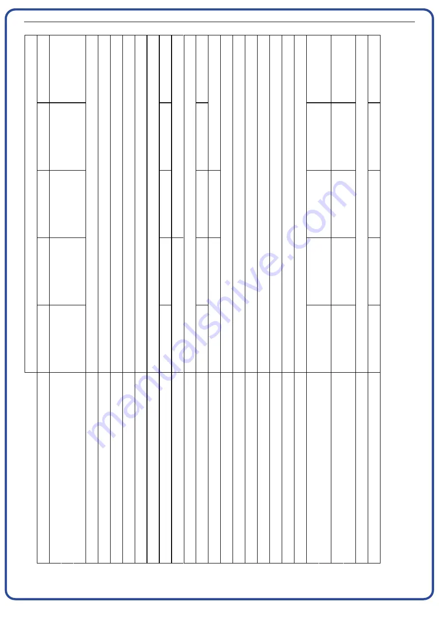
11.2 Technical data DRYPOINT RA 80-160 /AC

16

0

16

00

0

96

0

56

5

0,

15

2,

3

15

30

7,

0

29

00

15

,8

16

1

14

0

14

50

0

87

0

51

2

0,

13

2,

1

33

00

15

00

6,

8

25

50

14

,2

15

0

12

0

12

50

0

75

0

44

1

0,

07

G

2.

1/

2”

1,

85

25

00

13

80

6,

2

24

00

13

,8

14

1

10

0

10

50

0

63

0

37

1

0,

13

1,

30

11

50

5,

2

17

00

8,

0

94

A

ir

-c

o

o

le

d

80

81

00

48

6

28

6

+

3

eq

u

al

s

0,

73

g/

m

3

H

2

O

+

25

(+

50

)

+

1

+

35

(+

70

)

7

14

0,

09

G

2”

R

40

4

A

1,

25

19

00

-

-

-

-

-

-

1/

23

0-

24

0

/5

0

10

50

4,

9

15

00

7,

4

<

70

92

[l/

m

in

]

[m

3

/h

]

[s

cf

m

]

C

]

C

]

C

]

C

]

[b

ar

(g

)]

[b

ar

(g

)]

[b

ar

]

[B

S

P

-F

]

[k

g]

[m

3

/h

]

[m

3

/h

]

[m

3

/h

]

C

]

[b

ar

(g

)]

[B

S

P

-F

]

[P

h/

V

/H

z]

[W

]

[A

]

[W

]

[A

]

[d

bA

]

[k

g]

M

o

d

el

D

R

Y

P

O

IN

T

R

A

N

om

in

a

lc

ap

ac

ity

at

no

m

in

al

co

n

di

tio

n

1

P

re

ss

ur

e

de

w

po

in

t

at

no

m

in

al

co

nd

iti

on

1

N

om

in

a

la

m

bi

en

t

te

m

pe

ra

tu

re

(m

ax

.)

M

in

.

am

bi

en

tt

em

pe

ra

tu

re

N

om

in

a

li

nl

et

a

ir

te

m

pe

ra

tu

re

(m

ax

.)

N

om

in

a

li

nl

et

a

ir

pr

es

su

re

M

ax

.i

nl

e

ta

ir

pr

es

su

re

A

ir

pr

es

su

re

dr

op

-

p

In

le

t/o

u

tle

ta

ir

co

nn

ec

tio

ns

T

yp

e

of

re

fr

ig

er

a

nt

A

m

o

un

t

of

re

fr

ig

er

a

nt

3

C

oo

lin

g-

ai

r

fa

n

cu

rr

en

t

C

oo

lin

g-

w

at

er

vo

lu

m

e

flo

w

IN

:1

5

°C

,O

U

T

:3

C

C

oo

lin

g-

w

at

er

vo

lu

m

e

flo

w

IN

:3

0

°C

,O

U

T

:

40

°C

C

on

tr

o

lo

f

th

e

co

ol

in

g

w

at

er

flo

w

M

ax

im

um

w

at

er

te

m

pe

ra

tu

re

2

M

in

.

(m

ax

.)

w

a

te

r

pr

es

su

re

C

oo

lin

g-

w

at

er

co

nn

ec

tio

ns

S

ta

n

da

rd

po

w

er

su

pp

ly

3

E

le

ct

r.

no

m

in

al

ca

pa

ci

ty

N

om

in

a

lp

ow

er

co

ns

u

m

pt

io

n

50

H

z

M

ax

.e

le

ct

r.

p

ow

er

in

p

ut

M

ax

.p

o

w

er

co

ns

u

m

pt

io

n

5

0

H

z

M

ax

.s

ou

n

d

le

ve

la

t

1

m

W

e

ig

ht

1

T

h

e

n

o

m

in

a

l

c

o

n

d

it

io

n

re

la

te

s

to

a

n

a

m

b

ie

n

t

te

m

p

e

ra

tu

re

o

f

+

25

°C

w

ith

an

in

le

ta

ir

of

7

ba

r(

g)

an

d

+

35

°C

.

2

O

th

e

r

te

m

p

e

ra

tu

re

s

u

p

o

n

re

q

u

e

s

t.

3

C

h

e

c

k

th

e

in

d

ic

a

ti

o

n

s

o

n

th

e

ty

p

e

p

la

te

.

PNEUMATIG

Summary of Contents for DRYPOINT RA 100

Page 1: ...PNEUMATIG www pneumatig eu DRYPOINT RA 3 160 COMPRESSED AIR REFRIGERATION DRYER Instructions for installation and operation ...

Page 2: ... 534 Gdynia POLAND Phones 48 58 622 49 22 48 58 622 49 25 Fax 48 58 739 12 45 E mail pneumatig pneumatig com pl Our company is one of the most known pneumatic distributors in Poland More then 16 years of experience on the market is a solid package of experience which we successfully use as our advantage We keep an eye on the market and we can notice and urgently react on customers demands and intr...

Page 3: ...160 WC 22 12 Technical description 23 12 1 Control panel 23 12 2 Functional description 23 12 3 Flow diagram air cooled 24 12 4 Flow diagram water cooled 24 12 5 Refrigerating compressor 25 12 6 Condenser air cooled 25 12 7 Condenser water cooled 25 12 8 Cooling water controller 25 12 9 Filter dryer 26 12 10 Capillary tube 26 12 11 Aluminium heat exchanger 26 12 12 Hot gas bypass valve 26 12 13 Re...

Page 4: ...gram DRYPOINT RA 3 12 41 14 2 3 Exploded diagram DRYPOINT RA 18 23 42 14 2 4 Exploded diagram DRYPOINT RA 30 40 43 14 2 5 Exploded diagram DRYPOINT RA 55 60 44 14 2 6 Exploded diagram DRYPOINT RA 80 100 45 14 2 7 Exploded diagram DRYPOINT RA 120 160 46 14 3 Circuit diagrams 47 14 3 1 Circuit diagram diagram of the functional elements 47 14 3 2 Circuit diagram DRYPOINT RA 3 40 47 14 3 3 Circuit dia...

Page 5: ...is BM 0 mod_1183615737313_6 doc 4004 Pos 3 Beko Technische Dokumentati on Sicherheit Hi nweis Anlei tung BEKO 0 mod_1184147787557_6 doc 5758 Please check whether or not these instructions correspond to the device type Please adhere to all advice given in these operating instructions They include essential information which must be observed during installation operation and maintenance Therefore it...

Page 6: ...he fire Do not operate with open cover housing Maintenance works or controlling measures must only be carried out by qualified personnel 1 Do not smoke Note Pos 4 Beko Technische Dokumentati on Sicherheit Gefahr Druckluft 0 mod_1184148143854_6 doc 577 6 ARIA AIR LUFT AIR Connection point compressed air inlet ARIA AIR LUFT AIR Connection point compressed air outlet Connection point condensate drain...

Page 7: ...isk of serious injury or death through contact with quickly or suddenly escaping compressed air or through bursting and or unsecured plant components Compressed air is a highly dangerous energy source Never work on the dryer when the system is under pressure Never direct the compressed air outlet or condensate drain hoses at persons The user is responsible for the proper installation of the dryer ...

Page 8: ...ble Do not eat drink or smoke during work Keep out of the reach of children Breathing protection ambient air independent respirator at high concentrations Eye protection sealing goggles Hand protection protective gloves e g made of leather Personal protection protective clothing Skin protection use protective cream In addition the safety data sheet for the refrigerant needs to be observed Caution ...

Page 9: ...hibited The removal of sealings and leadings at safety devices is prohibited Operators of the devices must observe the local and national pressure equipment regulations in the country of installation Pos 8 Beko Technische Dokumentati on Sicherheit Sicher heitshi nweise weitere BM nicht Ex 0 mod_1183616103770_6 doc 4009os 9 Beko Technische D okumentati on Sicherheit Zusatz Sicher hei tshi nweise BM...

Page 10: ...al of the latter The category of the respective pressure device is indicated in the declaration of conformity For the examination prior to the start up and for periodic inspections the national regulations need to be observed such as the industrial safety regulation in the Federal Republic of Germany In countries outside the EU the respective regulations in force there need to be adhered to The pr...

Page 11: ...e with care Strong shocks can cause irreparable damage 8 Storage SCC0001 Keep the device away from extreme weather conditions even when packaged Keep the dryer in an upright position also while it is stored Tilting the device or turning it upside down can cause irreparable damage to some components When the dryer is not in use it can be stored in its pack aging in a dust free and protected place a...

Page 12: ...micals with a corrosive effect explosive gases toxic gases evaporation heat high ambient temperatures or extreme dust and dirt can be found Minimum installation requirements Choose an area which is clean and dry free from dust and protected against atmospheric disturbances The load bearing zone must be even horizontal and able to bear the weight of the dryer Minimum ambient temperature 1 C Maximum...

Page 13: ...tal consumption corresponds to the throughput rate of the compressor Installation type B is recommended when the air consumption constantly varies with peak values which considerably exceed the throughput rate of the compressor The storage capacity of the tank must be dimensioned in such a way that a possible short term high air demand peak air consumption can be compensated Note Contaminated inta...

Page 14: ...owing operating conditions Air inlet pressure 8 bar g Ambient temperature 45 C Air inlet temperature 50 C Pressure dew point 10 C Factor F1 1 05 Factor F2 0 88 Factor F3 0 70 Factor F4 1 37 Every data element has a corresponding numerical factor which multiplied with the nominal capacity is as follows Air throughput 240 x 1 05 x 0 88 x 0 70 x 1 37 212 m h 212 m h This is the maximum throughput rat...

Page 15: ...INT RA 80 100 2 345 DRYPOINT RA 120 160 2 1 2 410 Ø BPY0001 The dryer was designed in such a manner that vibrations that may occur during operation are limited Therefore it is advisable to employ connecting lines flexible hoses vibration inhibiting fittings etc which protect the dryer against possible vibrations in the pipework Note During the piping of the dryer the inlet and outlet connections n...

Page 16: ...les and the requirements of the local electricity supplier need to be con sidered Danger Supply voltage and missing earth connection Important ensure that the plant is connected to earth Do not use plug adapters at the power plug Possible replacement of the power plug must only be carried out by a qualified electrician 9 7 Condensate drain Danger Compressed air and condensate under pressure The co...

Page 17: ...livery this dryer was thoroughly tested packed and checked Please verify the soundness of the dryer dur ing the initial start up and check the perfect functioning during the first operating hours The initial start up must be carried out by qualified personnel During the installation and operation of this device all national regulations regarding electronics and any other federal and state ordinanc...

Page 18: ...te drain cycle is closed Ensure that the cooling water flow and the cooling water temperature are in accordance with the provisions water cooled Remove any packaging material and other items which may block the space around the dryer Establish the mains connection plug into wall socket Start the dryer by switching on the main switch on the control panel pos 1 Ensure that the DMC 14 electronics are...

Page 19: ...the DMC 14 electronics are switched on Wait for several minutes and then check whether or not the dew point temperature which is indicated on the display of the DMC 14 electronics is stable and whether or not the condensate is discharged at regular intervals Establish the compressed air supply During the operation the refrigerating compressor runs continuously The dryer needs to be switched on dur...

Page 20: ... H z W A W A dbA kg Model DRYPOINT RA Nominal capacity at nominal condition 1 Pressure dew point at nominal condition 1 Nominal ambient temperature max Min ambient temperature Nominal inlet air temperature max Nominal inlet air pressure Max inlet air pressure Air pressure drop p Inlet outlet air connections Type of refrigerant Amount of refrigerant 3 Cooling air fan current Cooling water volume fl...

Page 21: ... ambient temperature max Min ambient temperature Nominal inlet air temperature max Nominal inlet air pressure Max inlet air pressure Air pressure drop p Inlet outlet air connections Type of refrigerant Amount of refrigerant 3 Cooling air fan current Cooling water volume flow IN 15 C OUT 30 C Cooling water volume flow IN 30 C OUT 40 C Control of the cooling water flow Maximum water temperature 2 Mi...

Page 22: ...odel DRYPOINT RA Nominal capacity at nominal condition Pressure dew point at nominal condition 1 Nom ambient temperature max Min ambient temperature Nominal inlet air temperature max Nominal inlet air pressure Max inlet air pressure Air pressure drop p Inlet outlet air connections Type of refrigerant Amount of refrigerant 3 Cooling air fan current Cooling water volume flow IN 15 C OUT 30 C Cooling...

Page 23: ...the condensate drain Subsequently the cold and dry air is led through the air air heat exchanger so that it is reheated to up to 8 C below the inlet temperature when leaving the dryer Refrigeration cycle The refrigerant is conducted through the compressor and reaches a condenser under high pres sure There cooling down takes place making the refrigerant condense to a liquid state which is under hig...

Page 24: ...hanger 11 Capillary tube c Condensate drain 12 T1 temperature sensor dew point 2 Refrigerant pressure switch PB DRYPOINT RA 80 160 13 Condensate drain shut off valve 3 Safety temperature switch TS DRYPOINT RA 55 160 17 Electric control unit 4 Refrigerant pressure switch PA DRYPOINT RA 80 160 18 Condenser water cooled 5 Refrigerant fan pressure switch PV 19 Cooling water controller water cooled 6 R...

Page 25: ...t that the condenser unit is kept free from dust and other impurities 12 7 Condenser water cooled The condenser is the component in which the gas coming from the compressor is cooled down condensed and lique fied The water inlet temperature must not exceed the nominal values Likewise a correct flow must be ensured The water entering the condenser must be free from impurities 12 8 Cooling water con...

Page 26: ...rent the generous dimensions of the air refrigerant heat exchanger allow full evaporation of the refrigerant This prevents moisture from entering the refrigerating compressor The high performance condensate separator is inside of the heat exchanger module Maintenance is not necessary and the coalescence effect aims to achieve a high degree of moisture separation 12 12 Hot gas bypass valve At parti...

Page 27: ...reset PV Fan pressure switch which is installed on the pressure side of the refrigerating compressor It keeps the con densation temperature and pressure constantly in the range of the preadjusted limit values air cooled Adjusted pressure R 134 a Start 11 bar g 47 C Stop 8 bar g 36 C Tolerance 1 bar R 404 A Start 20 bar g 45 C Stop 16 bar g 36 C Tolerance 1 bar 12 14 Safety temperature switch Ts 1 ...

Page 28: ...lling of alarm situations of the dryer via a potential free contact on terminals 8 and 9 see enclosed circuit diagrams max 250V 1A min 5V DC 10mA the contact is open when the dryer is switched off or in an alarm condition and closed when the dryer is switched on and when the dew point is in accordance with the provisions OPERATING PRINCIPLE When the dryer has been switched on the electronic contro...

Page 29: ...nsmits a signal to the electronic control and a membrane solenoid valve opens to discharge the condensate The BEKOMAT closes before compressed air emerges Note These BEKOMAT condensate drains were designed in particular for the operation in a DRYPOINT RA refrigeration dryer The installation in other compressed air processing systems or the replacement with another drain marque can lead to disturba...

Page 30: ...Never direct the compressed air outlet or condensate drain hoses at persons The user is responsible for the proper maintenance of the dryer Non observance of the instructions in the Installation and Maintenance troubleshooting spare parts and dismantling chapters leads to the expiration of the guarantee Improper maintenance may result in dangerous situations for the personnel and or the device Dan...

Page 31: ...structions In addition the national and operational statutory provisions and safety regu lations as well as the accident prevention regulations required for the respective case of application need to be observed during employment This applies accordingly when accessories are used Danger Compressed air Risk of serious injury or death through contact with quickly or suddenly escaping compressed air ...

Page 32: ... is too low re establish the nominal conditions The inlet air throughput is higher than the throughput of the dryer reduce the flow rate re establish the nominal conditions The condenser is dirty please clean it air cooled The condenser fan does not work see the corresponding point air cooled The cooling water flow is insufficient re establish the nominal conditions water cooled The dryer does not...

Page 33: ...ryer If installed the TS safety tempera ture switch is trig gered Check which of the following reasons is responsible for the triggering 6 Excessive thermal load re establish the standard operating conditions 7 The inlet air is too hot re establish the nominal conditions 8 The ambient temperature is too high or the room ventilation insufficient ensure sufficient ventilation 9 The condenser unit is...

Page 34: ...SN 150 1 1 12 Dew point sensor T1 DMC14 XE RA 5625 NNN 035 1 1 1 1 1 1 1 1 17 DMC14 controller XE RA 5620 110 103 1 1 1 1 1 1 1 1 21 BEKOMAT 31 BM31 BI supply voltage 1 1 1 1 1 1 1 1 22 Main switch XE RA 5450 SZN 010 1 1 1 1 1 1 1 1 DRYPOINT RA 55 160 NO DESCRIPTION OF THE SPARE PARTS CODE 55 60 80 100 120 140 160 2 Refrigerant pressure switch PB XE RA 5655 NNN 085 1 1 1 1 1 3 TS safety temperatur...

Page 35: ...er Properties of the refrigerants Refrigerant Chemical formula TLV GWP R134a H FKW CH2FCF3 1000 ppm 1300 R404A H FKW CH2FCF3 C2HF5 C2H3F3 1000 ppm 3784 13 5 Dismantling of the dryer When the dryer is dismantled all parts and operating materials related to the plant need to be disposed of separately Component Material Refrigerant R404A R134a oil Roof and supports Structural steel epoxy paint coat R...

Page 36: ...GDYNIA UL WIELKOPOLSKA 158 58 622 49 22 Appendices 36 DRYPOINT RA 3 160 14 Appendices 14 1 Dryer dimensions 14 1 1 Dryer dimensions DRYPOINT RA 3 12 AC 14 1 2 Dryer dimensions DRYPOINT RA 18 23 AC P N E U M A T I G ...

Page 37: ...PNEUMATIG EU GDYNIA UL WIELKOPOLSKA 158 58 622 49 22 Appendices DRYPOINT RA 3 160 37 14 1 3 Dryer dimensions DRYPOINT RA 30 40 AC 14 1 4 Dryer dimensions DRYPOINT RA 55 60 AC P N E U M A T I G ...

Page 38: ...PNEUMATIG EU GDYNIA UL WIELKOPOLSKA 158 58 622 49 22 Appendices 38 DRYPOINT RA 3 160 14 1 5 Dryer dimensions DRYPOINT RA 80 100 AC 14 1 6 P N E U M A T I G ...

Page 39: ... UL WIELKOPOLSKA 158 58 622 49 22 Appendices DRYPOINT RA 3 160 39 14 1 7 Dryer dimensions DRYPOINT RA 55 60 WC 14 1 8 Dryer dimensions DRYPOINT RA 80 100 WC 14 1 9 Dryer dimensions DRYPOINT RA 120 160 WC P N E U M A T I G ...

Page 40: ...T RA 55 160 21 BEKOMAT condensate drain 4 Refrigerant pressure switch PA DRYPOINT RA 80 160 22 Main switch 5 Refrigerant pressure switch Ventilator PV 6 Refrigerating compressor 51 Front panel 7 Hot gas bypass valve 52 Back plate 8 Condenser air cooled 53 Right side panel 9 Condenser fan 54 Left side panel 9 1 Motor 55 Cover 9 2 Blades 56 Base plate 9 3 Grid 57 Upper plate 10 Filter dryer 58 Carri...

Page 41: ...PNEUMATIG EU GDYNIA UL WIELKOPOLSKA 158 58 622 49 22 Appendices DRYPOINT RA 3 160 41 14 2 2 Exploded diagram DRYPOINT RA 3 12 P N E U M A T I G ...

Page 42: ...PNEUMATIG EU GDYNIA UL WIELKOPOLSKA 158 58 622 49 22 Appendices 42 DRYPOINT RA 3 160 14 2 3 Exploded diagram DRYPOINT RA 18 23 P N E U M A T I G ...

Page 43: ...PNEUMATIG EU GDYNIA UL WIELKOPOLSKA 158 58 622 49 22 Appendices DRYPOINT RA 3 160 43 14 2 4 Exploded diagram DRYPOINT RA 30 40 P N E U M A T I G ...

Page 44: ...PNEUMATIG EU GDYNIA UL WIELKOPOLSKA 158 58 622 49 22 Appendices 44 DRYPOINT RA 3 160 14 2 5 Exploded diagram DRYPOINT RA 55 60 P N E U M A T I G ...

Page 45: ...PNEUMATIG EU GDYNIA UL WIELKOPOLSKA 158 58 622 49 22 Appendices DRYPOINT RA 3 160 45 14 2 6 Exploded diagram DRYPOINT RA 80 100 P N E U M A T I G ...

Page 46: ...PNEUMATIG EU GDYNIA UL WIELKOPOLSKA 158 58 622 49 22 Appendices 46 DRYPOINT RA 3 160 14 2 7 Exploded diagram DRYPOINT RA 120 160 P N E U M A T I G ...

Page 47: ...DMC14 Electronic controller compressed air dryer PR T1 Temperature sensor dew point PV Pressure switch fan control PA Pressure switch compressor pressure side high pressure DRYPOINT RA 80 160 PB Pressure switch compressor suction side low pressure DRYPOINT RA 80 160 TS TS safety temperature switch DRYPOINT RA 55 160 BOX Electric cabinet ELD BEKOMAT condensate drain BN BROWN BU BLUE BK BLACK YG YEL...

Page 48: ...V max 250V 1A 8 9 T1 11 12 M M C KT CS Bn Air Dryer Controller Bn C S R SEL0017 min 5VDC 10mA Air Dryer Controller DEW POINT ALARM 14 3 4 Circuit diagram DRYPOINT RA 80 160 Air Dryer Controller 3 3 2 4 5 11 12 2 POWER M CV Bn Bn 3 2 1 9 DEW POINT ALARM max 250V 1A T1 8 KT R CS S M C C min 5VDC 10mA SEL0018 Air Dryer Controller DEW POINT ALARM P N E U M A T I G ...

Page 49: ... 60 AC 37 Dryer dimensions DRYPOINT RA 80 100 AC 38 Dryer dimensions DRYPOINT RA 80 100 WC 39 E Electrical connections 16 Exclusion from a field of application 10 Exclusion of an application 10 Exploded diagram 40 Exploded diagram DRYPOINT RA 80 100 45 Exploded diagram DRYPOINT RA 120 160 46 Exploded diagram DRYPOINT RA 18 23 42 Exploded diagram DRYPOINT RA 30 40 43 Exploded diagram DRYPOINT RA 3 ...

Reviews: