Installation and operating manual
EN
10 BEKOMAT
®
3/6 CO Ex, 3/6 E Ex
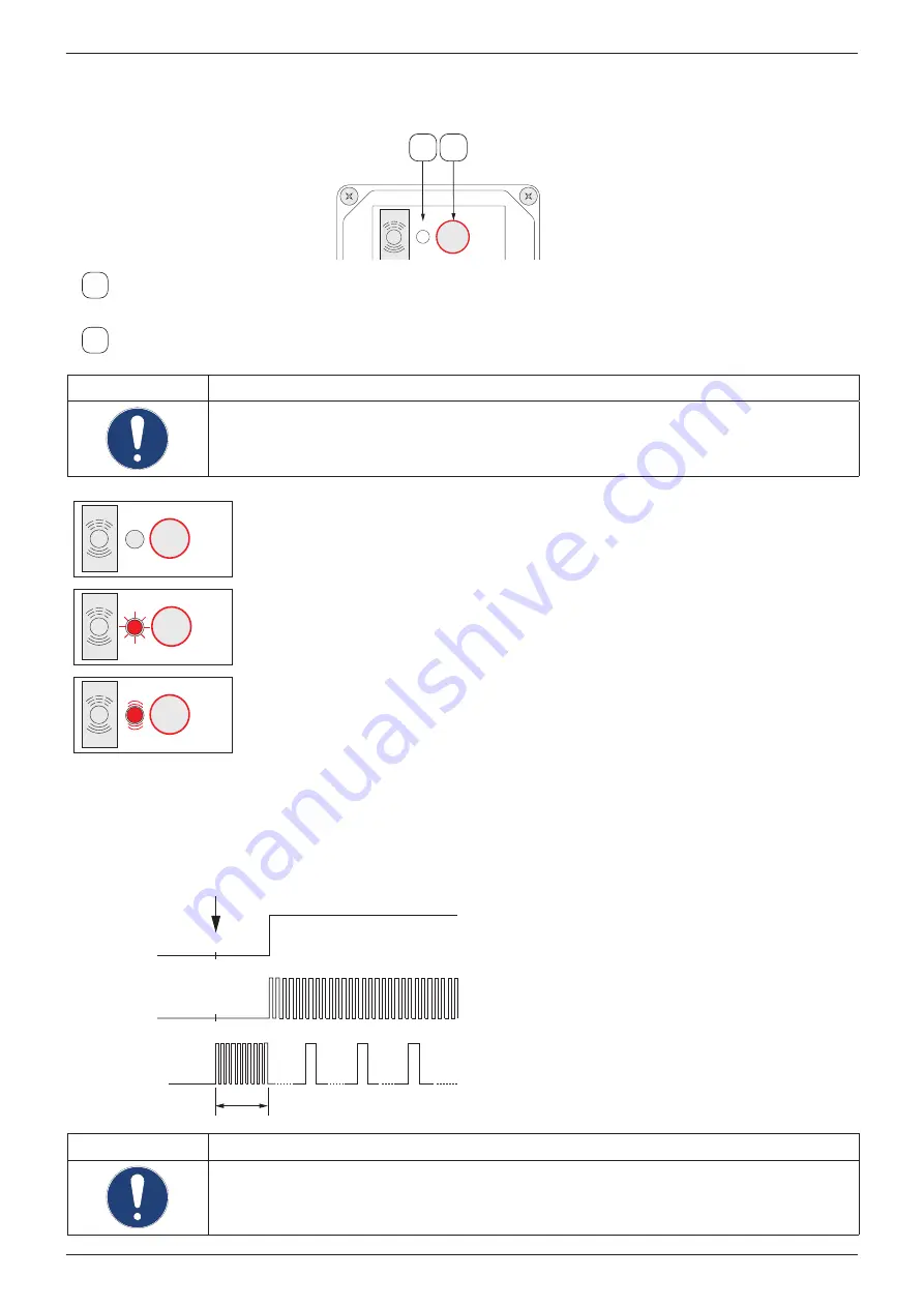
2.3. Control and display elements
The control and display elements of the BEKOMAT
®
are integrated into the electronics housing.
BEKO TECHNOLOGIES
www.beko-technologies.com
BEKOMAT
®
ALARM / TEST
NETZ / POWER
TEST
1 2
1
Alarm /test LED
Indicates the current system state of the BEKOMAT
®
.
2
Test button
Press this button to depressurise or manually drain the BEKOMAT
®
.
NOTE
No permanent drainage
Do not use the test button for permanent drainage!
ALARM / TEST
NETZ / POWER
TEST
Alarm/test LED off
BEKOMAT
®
is not powered.
ALARM / TEST
NETZ / POWER
TEST
Alarm /test LED lit
BEKOMAT
®
is powered and running in normal operating mode.
ALARM / TEST
NETZ / POWER
TEST
Alarm /test LED flashing
BEKOMAT
®
is in alarm mode or test button has been pressed.
Alarm mode:
The BEKOMAT
®
is continuously monitored by electronic and sensory devices. If a fault or malfunction occurs, the BEKOMAT
®
is
automatically switched to alarm mode (e.g. due to blocked condensate discharge, or overload). In alarm mode, the solenoid valve is
automatically opened, starting in cycle mode in order to eliminate the problem. If the problem persists for more than one minute, the
red alarm LED flashes and the optocoupler output is switched. The valve is then repeatedly opened every four minutes for 7.5 seconds,
until the problem is resolved automatically or by servicing the unit. After the problem has been resolved, the BEKOMAT
®
automatically
switches to normal operating mode.
1 min
4 min
Ventil
Alarm-LED
Optokoppler-
Ausgang
Alarmmodus
7,5 s
7,5 s
7,5 s
4 min
4 min
3 min
NOTE
Additional information
For additional information regarding the function of the BEKOMAT
®
11.


