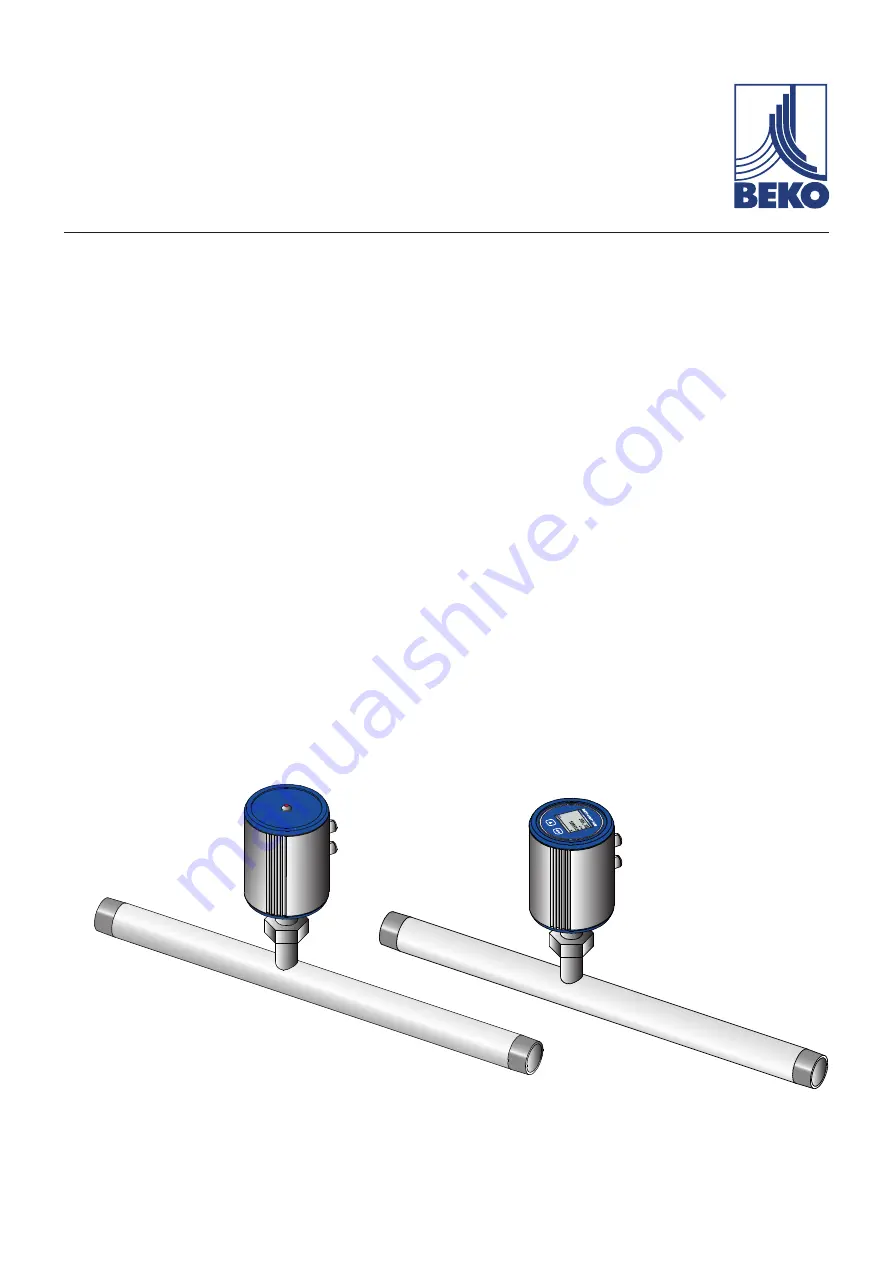
background image

C

A

LIBRATION

METPOINT

®

 FLM SF13

FLMSF13LD8 | FLMSF13DD8 | FLMSF13LD15 | FLMSF13DD15 | FLMSF13LD20 | FLMSF13DD20 | FLMSF13LD25 |  

FLMSF13DD25 | FLMSF13LD32 | FLMSF13DD32 | FLMSF13LD40 | FLMSF13DD40 | FLMSF13LD50 | FLMSF13DD50

Thermal flow meter

Installation and operating manual

EN - English

10-205

Summary of Contents for 4036460

Page 1: ...LMSF13LD8 FLMSF13DD8 FLMSF13LD15 FLMSF13DD15 FLMSF13LD20 FLMSF13DD20 FLMSF13LD25 FLMSF13DD25 FLMSF13LD32 FLMSF13DD32 FLMSF13LD40 FLMSF13DD40 FLMSF13LD50 FLMSF13DD50 Thermal flow meter Installation and operating manual EN English 10 205 ...

Page 2: ...s 13 2 6 Technical data 14 2 7 Measuring ranges 15 2 7 1 For air 15 2 7 2 For other gases 15 3 Installation 16 3 1 Warning 16 3 1 1 Requirements for piping 16 3 1 2 Requirements for inlet outlet sections 16 3 1 3 Turning housing 17 4 Electrical installation 18 4 1 Pin assignment of plug type connectors 18 4 2 Connection options 18 4 2 1 Bidirectional RS485 bus system 18 4 2 2 Current output 4 20 m...

Page 3: ...7 6 3 4 Entering reference conditions 28 6 3 5 Setting zero point for low flow cut off function 29 6 4 ModBus setup 30 6 4 1 ModBus settings 2001 2005 31 6 4 2 Values register 1001 1500 31 6 5 Pulse alarm 32 6 5 1 Pulse output 32 6 6 User Setup 33 6 7 Advanced 33 6 8 4 20 mA 34 6 9 Info 35 6 10 MBus 35 6 10 1 Default communication settings 35 6 10 2 Transferred values 35 7 Spare parts and accessor...

Page 4: ...2 On the device General instructions General hazard symbol danger warning caution Observe installation and operating instructions on type plate 1 2 Signal words DANGER Imminent danger Consequences of non compliance serious or even fatal injury WARNING Potential danger Consequences of non compliance serious or even fatal injury CAUTION Imminent danger Consequences of non compliance injury and or da...

Page 5: ...trictly adhered to All components of the electrical installation on site must be approved and or bear the CE mark A reliably accessible circuit breaker e g power plug or switch that shuts off all conductors must be installed close to the unit WARNING Operation of device outside limit range If the specified limits are exceeded there is a risk of device malfunction potentially resulting in injury an...

Page 6: ...rised and suitably trained technical personnel If you detect any damage do not start the device Adhere to the permissible storage and transport temperatures see technical data Protect the device against direct sunlight and heat radiation The device must be stored in the original packaging Seal the packaging and store it in a dry and frost free room Ensure that the storage temperature does not exce...

Page 7: ...pecified in the technical data Do not operate the device with any media fluids gas vapour mixtures other than those listed above Any other use of the device is deemed improper and poses a risk to persons property and the environment 1 6 Warranty and liability All warranty shall be voided if the METPOINT FLM is used improperly for a purpose other than the intended or is operated outside the limits ...

Page 8: ... hand when contacting the manufacturer or supplier Designation Description METPOINT FLM SF13 Type designation S N 12579143 Serial number P N 4036460 Product number Gas air Medium Supply 18 36 VDC Power supply rating 0 90 m h Min max measuring range 4 20 mA Min max current output Diameter DN50 Rated diameter of measuring section Pmax 16 bar Max permissible operating pressure NOTICE Handling of type...

Page 9: ... Product overview and description 2 3 1 Identification based on product code R R FLM Rated diameter of measuring section R Version with LED Interface RS485 Operating pressure 16 bar SensorFlow model designation FlowMeasurement product designation SF 13 L D20 ...

Page 10: ...s equipped with a Modbus RTU RS485 interface a 4 20 mA current output a galvanically isolated pulse output and an optional MBus interface 2 3 3 Operating principle Two temperature sensors are installed in series in the direction of flow The first temperature sensor measures the current process temperature while the second sensor is electrically heated to a temperature that is exactly 40 K above th...

Page 11: ...res a LED calibration indicator mounted at the top of the housing After 15 months the LED begins to flash indicating that the device needs to be calibrated The flashing LED does not have any effect on the measuring process and the device continues to provide accurate measuring signals On request the calibration interval can be adjusted at the factory METPOINT FLM FLOW MEASURING HW 1 00 SW 1 00 AIR...

Page 12: ...The direction of flow is indicated by the arrows 1 on the housing of the METPOINT FLM and on the sensor tube 1 NOTICE Additional information If necessary turn the housing e g to change the direction of flow through the device For more information see Turning housing auf Seite 17 ...

Page 13: ...mensions Version with display Version with LED A G ISO 228 1 C mm 80 F mm 94 G mm 102 105 5 Measuring section dimensions DN8 DN15 DN20 DN25 DN32 DN40 DN50 R R R R R1 R1 R1 R2 H1 mm 186 7 186 7 186 7 186 7 186 7 186 7 186 7 H mm 193 6 197 4 200 2 203 5 207 9 210 9 216 9 L1 mm 137 210 275 275 275 275 275 L mm 194 300 475 475 475 475 475 ...

Page 14: ...on Current output Measuring section DN8 R 4 20 mA 0 90 l min Measuring section DN15 R 0 90 m h Measuring section DN20 R 0 170 m h Measuring section DN25 R1 0 290 m h Measuring section DN32 R1 0 530 m h Measuring section DN40 R1 0 730 m h Measuring section DN50 R2 0 1195 m h Pulse output Floating switch contact Passive max 48 VDC 150 mA 1 pulse per m or per litre Unit adjustable at display Accuracy...

Page 15: ...andard DIN 1945 ISO 1217 20 C 1000 mbar and compressed air 2 7 2 For other gases 1 1 1 2 2 3 Current output 20 mA Current output 20 mA Current output 20 mA Current output 20 mA Current output 20 mA Current output 20 mA Current output 20 mA Current output 20 mA Current output 20 mA l min m h m h m h m h m h m h m h m h Reference standard DIN 1945 ISO 1217 20 C 1000 mbar reference values for sensor ...

Page 16: ...d flanges and gaskets Differences in pipe diameters at joints should not exceed 1 mm For more information see ISO 14511 Clean properly installed pipes 3 1 2 Requirements for inlet outlet sections The table below shows the required inlet pipe sections with reference to the direction of flow Table of additional inlet pipe sections required in specific cases Flow obstruction upstream of measuring sec...

Page 17: ... direction the housing can be turned by 180 by loosening the 4 setscrews with 1 5mm hexagon sockets Align the housing as required and tighten the setscrews again by hand NOTICE Risk of damage to device Ensure that the connecting pipes are correctly mounted and that the gaskets are installed properly ...

Page 18: ... 61076 2 101 Pin assignment of connector Transmitter side Pin assignment of connector Socket side Pin assignment of connector Screw side 4 2 Connection options 4 2 1 Bidirectional RS485 bus system Connection by means of plug type connector A Connection diagram for METPOINT SF13 q METPOINT FLM SFxx 1 2 4 3 RS485 A B V U V U V U V U RS485 MODBUS V Pin assignment sensor Function Wire colour PIN 1 UV ...

Page 19: ...PIN 1 UV Plus connection power supply brown PIN 2 not assigned white PIN 3 UV Minus connection power supply blue PIN 4 not assigned black PIN 5 IOUT Current output grey 4 2 3 Mbus optional Connection by means of plug type connector B Connection diagram for METPOINT SF13 q METPOINT FLM SFxx 1 4 5 3 MBus V U V U V U V U MBus V Pin assignment sensor Function Wire colour PIN 1 not assigned brown PIN 2...

Page 20: ... Galvanically isolated pulse grey 4 3 Connection of METPOINT BDL 4 3 1 Bidirectional RS485 bus system Connection by means of plug type connector A Connection diagram for METPOINT SF13 and METPOINT BDL METPOINT FLM SFxx METPOINT BDL BROWN WHITE q BLUE BLACK 1 3 2 4 1 2 3 4 5 6 7 8 9 V U V A B RS485 V U Pin assignment sensor Function Wire colour Pin assignment BDL PIN 1 UV Plus connection power supp...

Page 21: ...IOUT Current output grey PIN 4 Analog IN PIN 3 UV Minus connection power supply blue PIN 8 UV PIN 2 not assigned white PIN 4 not assigned black 4 3 3 Galvanically isolated pulse output Connection by means of plug type connector B Connection diagram for METPOINT SF13 and METPOINT BDL METPOINT FLM SFxx METPOINT BDL q R 4 7kΩ BROWN BLACK GREY BLUE 1 4 5 3 Impuls V U V U V U V U V 1 2 3 4 5 6 7 8 9 R ...

Page 22: ...wer supply blue PIN 2 UV PIN 2 A Non inverted signal from RS485 interface white PIN 7 RS485 A PIN 4 B Inverted signal from RS485 interface black PIN 8 RS485 B PIN 5 not assigned grey 4 4 2 Current output 4 20 mA 3 wire Connection by means of plug type connector A Connection diagram for METPOINT SF13 and METPOINT BDL compact analog board METPOINT FLM SFxx METPOINT BDL compact Analogboard BROWN BLUE...

Page 23: ... sensor Function Wire colour Pin assignment BDL compact PIN 1 UV not assigned brown PIN 4 Pulse Pulse black PIN 1 UV PIN 5 Pulse Pulse grey PIN 8 V PT PIN 3 UV not assigned blue PIN 2 not assigned white 4 5 Modbus termination If the METPOINT FLM is the last device in the Modbus system it must be terminated The sensor is equipped with a built in terminator To terminate the device loosen the 2 top s...

Page 24: ... is displayed The device menus are operated through two capacitive buttons UP ENTER 6 1 Display during operation Gasart Statusmeldung HW Version SW Version Modbus ID Seiten Nr CAL indicates that calibration is due After 15 months message CAL is displayed indicating that the device needs to be calibrated This message does not have any effect on the measuring process and the device continues to prov...

Page 25: ...rd factory settings 0000 4 x zero If required change the password by selecting Setup User Setup Password Press the UP button to select and to change a value Press the ENTER button to confirm the selection or change 6 3 Sensor Setup Setup Sensor Setup 53 1 mm To make a change select the respective menu option using the UP button and confirm by pressing the ENTER button ...

Page 26: ...nter the new value and confirm by pressing the ENTER button 6 3 2 Entering changing consumption counter value Setup Sensor Setup Total Counter To change the unit press the UP button to select the Unit field and confirm by pressing the ENTER button Press the UP button to select the desired unit and confirm by pressing the ENTER button 2x Press the UP button to select the value to be changed and con...

Page 27: ...e Setup Sensor Setup Units To change the unit press the UP button to select the Unit field and confirm by pressing the ENTER button If there are more possible units that fit on the screen press the button to call up the next screen Press the UP button to select the desired unit and confirm by pressing the ENTER button 2x ...

Page 28: ...reference pressure press the UP button to select the Unit field and confirm by pressing the ENTER button Press the UP button to select the desired unit and confirm by pressing the ENTER button 2x Setup Sensor Setup Ext Setup Ref Temp Enter the reference temperature Setup Sensor Setup Ext Setup Filtertime Under Filtertime you can enter an attenuation provided that a Filtergrade is entered Possible ...

Page 29: ...point press the CLR button To return to the previous screen press the Back button Setup Sensor Setup ZP Adjust CutOff The low flow cut off function is used to set consumption rates below the entered low flow cut off point to 0 m h so that they do not cause the consumption counter value to increase To delete the cut off point press the CLR button To return to the previous screen press the Back butt...

Page 30: ...tup Save the settings by pressing the Save button To apply the default factory settings press the Set to Default button ModBus default settings ModBus ID 1 Baud rate 19200 Stop bit 1 Parity even Caution If the sensor is the last device in the Modbus system it must be terminated The sensors are equipped with a built in terminator To activate termination loosen the 2 setscrews of the housing remove ...

Page 31: ...1140 4 Float Flow in Nltr h R X 1149 1148 4 Float Flow in ltr min R X 1157 1156 4 Float Flow in Nltr min R X 1165 1164 4 Float Flow in ltr s R X 1173 1172 4 Float Flow in Nltr s R X 1181 1180 4 Float Flow in cfm R X 1189 1188 4 Float Flow in Ncfm R X 1197 1196 4 Float Flow in kg h R X 1205 1204 4 Float Flow in kg min R X 1213 1212 4 Float Flow in kg s R X 1221 1220 4 Float Flow in kW R X 1269 1268...

Page 32: ... pulse output kg cd l m Select Value to enter the pulse factor 0 1 1 10 100 Select Polarity to enter the switching state plus 0 1 minus 1 0 6 5 1 Pulse output The maximum permissible number of pulses per second is 50 Pulse output is delayed by 1 second Pulse factor m h m min l min 0 1 l pulse 18 0 3 300 1 l pulse 180 3 3000 0 1 m pulse 18000 300 300000 1 m pulse 180000 3000 3000000 Table 1 Maximum...

Page 33: ...tate the display and adjust its brightness Password change password Backlight adjust brightness Rotate rotate display To change the password you must enter the new password twice The password must consist of 4 numerical digits 6 7 Advanced Setup Advanced Press the Factory Reset button to reset the METPOINT FLM to its default factory settings ...

Page 34: ...hows the available units for flow Press the button to call up the next screen The scaling of the 4 20 mA current output can be set to automatic AutoRange on or manual AutoRange off With AutoRange on the sensor automatically calculates the valid measuring range and associated reference conditions based on the set pipe diameter Select Scale 4mA and Scale 20mA to manually configure the scaling of the...

Page 35: ...g range 20 mA to 20 5 mA value above measuring range Confirm your entry by pressing the ENTER button 6 9 Info Setup Info This screen shows device information Press Details to view the calibration conditions 6 10 MBus 6 10 1 Default communication settings Primary address 1 ID Serial number of sensor Baud rate 2400 Medium Gas 6 10 2 Transferred values Value 1 with Unit Flow m h Value 2 with Unit Con...

Page 36: ...water with a little detergent Do not clean the sensor with a cloth sponge brush or other implement as any mechanical impact can destroy the sensor In the event of persistent deposits return the sensor to the manufacturer for inspection and cleaning 10 Calibration If the device is not custom configured we recommend having it calibrated every 12 months For calibration send the METPOINT FLM to BEKO T...

Page 37: ...EN Installation and operating manual 37 METPOINT SF13 12 Declaration of Conformity ...

Page 38: ... max operating temperature 30 C 80 C Data sheet DB_FLM 0916 FP A Product description and function Thermal flow meter for compressed air Pressure Equipment Directive 2014 68 EU The products are not classified in any pressure equipment category In accordance to article 4 section 3 they have been designed and manufactured according to sound engineering practice as applicable in the EU member states E...

Page 39: ...EN Installation and operating manual 39 METPOINT SF13 ...

Page 40: ...2 76 68 Mobil 34 610 780 639 info es beko technologies es BEKO TECHNOLOGIES LIMITED Room 2608B Skyline Tower No 39 Wang Kwong Road Kwoloon Bay Kwoloon Hong Kong Tel 852 2321 0192 Raymond Low beko technologies com BEKO TECHNOLOGIES INDIA Pvt Ltd Plot No 43 1 CIEEP Gandhi Nagar Balanagar Hyderabad IN 500 037 Tel 91 40 23080275 91 40 23081107 Madhusudan Masur bekoindia com service bekoindia com BEKO ...

Reviews: