background image

Safety Precautions

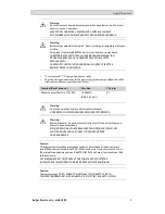
Warning:

Do not disconnect equipment unless power has been removed or the area is
known to be non-hazardous
AVANT DE DECONNECTER L’EQUIPEMENT, COUPER LE COURANT
OUS’ASSURER QUE L‘EMPLACEMENT EST DESIGNE NON DANGEREUX.

Warning:

Battery may explode if mistreated. Do not recharge, disassemble or dispose
of in

fi

re.

This product contains a BR2330A battery that is not user replaceable.
LA BATTERIE PEUT EXPLOSER EN CAS DE MAUVAISE MANIPULATION.
NE LA RECHARGEZ PAS, NE LA DÉMONTEZ PAS ET NE LA JETEZ
PAS DANS LE FEU.
CE PRODUIT CONTIENT UNE PILE BR2330A QUI NE PEUT PAS ÊTRE
REMPLACÉE PAR L'UTILISATEUR.

Use minimum 75°C copper conductors only.

To make wiring connections to the power supply connector, follow the table
with cable and torque specifications below:

Terminal Block Connector

Wire Size

TQ Lb.In.

Phoenix Contact Part No. 1757022

14–20 AWG
(2.08–0.52 mm

2

)

5–7

Warning:

Do not open when an explosive atmosphere is present.
N'OUVREZ PAS SI UNE ATMOSPHÈRE EXPLOSIVE EST PRÉSENTE.

Warning:

Explosion hazard! Do not disconnect while circuit is live unless the area is
known to be non hazardous.
RISQUE D'EXPLOSION ! NE DÉBRANCHEZ PAS LORSQUE LE CIRCUIT EST
SOUS TENSION SAUF SI LA ZONE EST CONNUE POUR ÊTRE
NON DANGEREUSE.

Caution:

This equipment is tested as a component and is to be installed inside an enclosure
rated IP54 minimum if used in an ATEX/IECEx Zone 2 area. However, since the unit is
IP66 rated it can be deployed in an IP66 ATEX/IECEx Zone 2 area if enclosed in an IP66
rated enclosure.
CET ÉQUIPEMENT EST TESTÉ EN TANT QUE COMPOSANT ET DOIT ÊTRE
INSTALLÉ DANS UN BOÎTIER AVEC INDICE DE PROTECTION IP66 MINIMUM.

Caution:

Temperature code T4 IEC/EN 60079-0 (2012) and IEC/EN 60079-15 (2010).
CODES DE TEMPÉRATURE T4 IEC/EN 60079-0 (2012) ET IEC/EN 60079-15 (2010).

Beijer Electronics, MAEN185

5

Summary of Contents for T7BR

Page 1: ...T7BR Installation Manual English MAEN185 2015 02...

Page 2: ...roup companies assumes no responsibility for any errors that may appear in this document Read the entire installation manual prior to installing and using this equipment Only quali ed personnel may in...

Page 3: ...calData 13 4 ChemicalResistance 15 4 1 MetalCasing 15 4 2 Touch Screen and Overlay Material 16 4 2 1 Auto ex EB 16 4 2 2 Touch Screen Surface 17 4 2 3 Touch Screen Protector 17 4 3 Terminalto PanelGas...

Page 4: ...e open ush with plenty of water and get medical attention The gures in this manualserves an illustrative purpose Because of the many variables associated with any particular installation the supplier...

Page 5: ...Size TQ Lb In Phoenix Contact Part No 1757022 14 20 AWG 2 08 0 52 mm2 5 7 Warning Do not open when an explosive atmosphere is present N OUVREZ PAS SI UNE ATMOSPH REEXPLOSIVE EST PR SENTE Warning Expl...

Page 6: ...ompanyinginstallation instructions Onlyquali ed personnel may install the operatorpanel Separate the high voltage signal and supply cables Make sure that the voltage and polarity of the powersource is...

Page 7: ...e operatorpanel orparts thereofshall be recycledaccording to local regulations The followingcomponentscontain substancesthat might be hazardous tohealth and the environment lithiumbattery electrolytic...

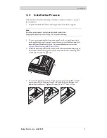
Page 8: ...e Requirements Maximum installation plate thickness 7 mm Space requirements in millimeterswhen installingthe operatorpanel 100 204 100 100 50 143 50 mm Note The dimensions on the drawing are not propo...

Page 9: ...n the outline drawing Aseparate cut out drawingis available for download from the Beijer Electronics web site Formore information see sections Operator Panel Drawings and Technical Data 3 Installthe o...

Page 10: ...connecting it to the power outlet Ensure that the operator panel and the controller system have the same electrical grounding reference voltage level otherwise errors in communication may occur Ensur...

Page 11: ...take care to avoid static electricitythat could damage the panel 2 2 1 Connections to the Controller For information aboutthe cables to be used when connecting the operator panelto the controller ple...

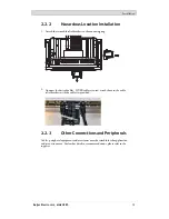
Page 12: ...cables If USBcables are used attach themtothe cable relief brackets with the cable tiesprovided 2 2 3 Other Connections and Peripherals Cables peripheral equipment and accessories must be suitable fo...

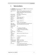
Page 13: ...9 pin D sub contact with RS232 RTS CTS chassis mounted female with standard locking screws 4 40 UNC Communication module CAN Ethernet 1 10 100 Base T shielded RJ45 1 10 100 1000 Base T shielded RJ45 U...

Page 14: ...www beijerelectronics com UL approval Yes 61010 2 201 UL 508 replacement 1 See section Chemical Resistance for more information 2 Standby mode The backlight is turned off there are no cabled interface...

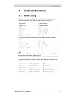
Page 15: ...llowing chemicals at room temperature Butanol Nitric acid 3 Hydrochloric acid 5 Nitric acid 10 Isopropyl alcohol Phosphoric acid 43 Sodium hypochlorite 10 Turpentine Note If exposure to any of the abo...

Page 16: ...SBP 60 95 1 Bleach 1 Hydrochloric acid 36 Sulfuric acid 10 Castor oil Linseed oil Tomato ketchup Caustic soda 40 1 Methanol Trichloroaceticacid 50 Cutting oil Nitric acid 10 White Spirit Cyclohexanol...

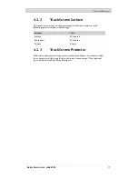
Page 17: ...out visible change Solvents Time Acetone 10 minutes Isopropanol 10 minutes Toluene 5 hours 4 2 3 Touch Screen Protector For harsh environments and exposure tooutdoorconditions it isrecommended to use...

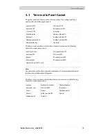
Page 18: ...to the following chemicalsat room temperature Acetic acid conc Na hypochlorite 10 Ammonia 30 Nitric acid 10 Butanol Phosphoric acid 10 Ethyl acetate Phosphoric acid 20 Hydrochloric acid 37 cold Note...

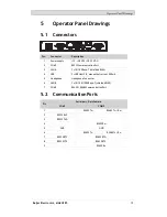
Page 19: ...USB 2 USB Host 2 0 max output current 500 mA 5 Headphone Headphone Connector 6 LAN B 1 x 10 100 1000 Base T shielded RJ45 7 COM2 RS422 RS485 Communication Port 5 2 Communication Ports Serial port 9 pi...

Page 20: ...elDrawings 5 3 T7BR Outline mm 204 143 A 7 max 8 66 B 188 127 9 9 D C B A Connectors B OptionalCAN module not shown C USB host D SD memory card slot CAN depth doesnotexceed heatsink Beijer Electronics...

Page 21: ...o local electricalcodes between the quick connect terminalconnectoron the operatorpanel and the chassis of the panel see 2 in drawing above 2 Connect awire orgroundingbraid that is sized correctlyacco...

Page 22: ...5 RJ45 RJ45 RJ45 Industrial Ethernet Operator panel Operator panel Operator panel Operator panel Shielded Short and unshielded 0 1 F 250 V 1 1 3 3 8 8 2 2 In some industrialunits forEthernet the RJ45...

Page 23: ...n istobreak the shield see 3 in drawing above A more elegant methodistoexpand the shielded Ethernet cablingwith a piece of unshielded Ethernetcable see 4 in drawingabove The shield canbe grounded via...

Page 24: ...shield to the ground via a 0 1 F 250 V plastic capacitor Both ends are then connected tothe ground in terms ofHF but only connected to the ground at one end in terms ofLF thus avoidingthe 50 60 Hz gro...

Page 25: ...t in halfwith an 8 10 C increase in temperature A 15 20 C temperature increase results ina quarter ofthe lifespanetc Rittal has a goodprogram for estimatingthe anticipated average temperature in the c...

Page 26: ...LVaccording to EN 60950 protection against electric shock andUL 950 Note Here is an example that explains why a secure 24 V DC feed can be ruined by mixing 24 V relay contacts with 230 V AC relay cont...

Page 27: ...al Many peripherals includingUSBdevices bond the signal ground 0 V ofthe terminal to the protective earth ground Bondingsignal groundand protective earth ground may increase electrical emissions and i...

Page 28: ...the ground potential the shield should be connected tothe ground via 0 1 F 250 V plastic capacitorto preventground current in the braided shield A numberof manufacturers recommendthat the shield be g...

Page 29: ...Head office Beijer Electronics AB Box 426 201 24 Malm Sweden www beijerelectronics com 46 40 358600...

Reviews: