background image


Loader arm 


Type: WLA60 

 Version: 1 

July 2019 


Page 15 van 23 


5.


Operations


5.1.


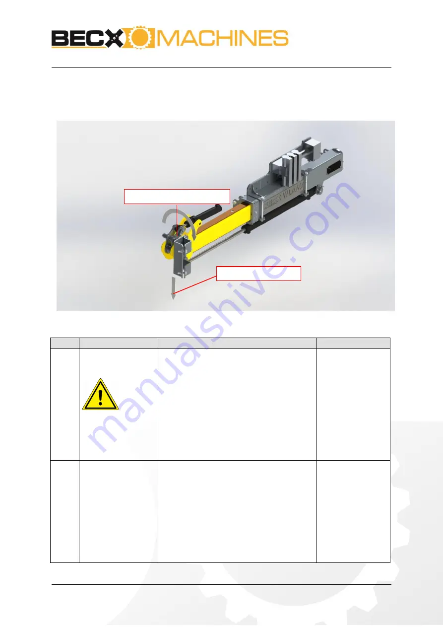
Assembly and adjustment of the loader arm 


 Figure 7: maximum forces arm and tool 


No. 

What to do 

Action 

Result 

Select the correct tool 
carrier and lifting arm 


Make sure that the tool carrier and lifting 
arm are sufficiently strong and stable for 
the weed brush (see chapter 1: Technical 
data 
for the load when lifting and the 
exerted moment of the lifting). 


Make sure that the maximum pressure 
and number of revolutions (oil flow) are 
not exceeded. 


Make sure that the correct rapid 
attachment connections are installed. 


Make sure that the correct clasp is used. 

Ignoring the stated 
values can result in 
damage to 
equipment and 
injury to persons. 
  

Connect the loader 
arm to the loader 
mechanically 


Make sure the base is vertical 


Connect the adapter plate (Figure 
3:
3) with at least 4 of the provided 12 
connection holes to the loader. 


Place the base (Figure 3:6) on the 
desired position on the adapter plate. 
Depending on the preference of the 
user, it can be mounted on different 
positions. 


Lock the base properly 


Moment tool 

Vertical force tool 

Summary of Contents for WLA60

Page 1: ...Loader arm Type WLA60 Version 1 July 2019 Loader arm WLA60 User Manual ...

Page 2: ...rding tape electronically or by any other means without prior written permission from Becx Machines B V Becx Machines B V reserves the right to modify parts of the system including the contents of this manual at any moment without prior or direct notification to the buyer Although Becx Machines B V has taken the greatest care to make sure that individual parts have been described correctly and in ...

Page 3: ...mounted to the front or rear of your machine Combined with the lift of your wheel loader this allows you cut nearly every hedge The WLA60 can carry our HS130HR and HS150HR hedge cutters and even our new HS131HR hedge cutter Carefully read this manual before using the loader arm Always follow the safety instructions set out in chapter 3 One copy of this manual must be kept with the loader arm and m...

Page 4: ...SE PARTS LOADER ARM 13 4 HYDRAULIC SCHEMES 14 5 OPERATIONS 15 5 1 ASSEMBLY AND ADJUSTMENT OF THE LOADER ARM 15 5 2 CARRY OUT THE WORKS 16 6 MAINTENANCE 17 7 FAILURE ANALYSES 18 8 REMOVAL 19 9 LOGBOOK 20 9 1 MAINTENANCE SERVICING REPAIRS REPLACEMENTS FAULTS AND INSPECTIONS 20 Figures FIGURE 1 OVERVIEW 10 FIGURE 2 ATTACHMENT PLATE 11 FIGURE 3 GENERAL OVERVIEW OF THE MECHANICAL COMPONENTS 12 FIGURE 4...

Page 5: ...rectives Machinery Directive 2006 42 EC Complies with the following standards NEN EN 12100 1 Safety of machinery Basic definitions general design principles Part 1 Basic terminology methodology NEN EN 12100 2 Safety of machinery General design principles Part 2 Technical principles and descriptions NEN EN 982 Safety of machines Safety requirements for hydraulic and pneumatic systems and their comp...

Page 6: ...July 2019 Page 6 van 23 List of symbols This manual uses the following symbols for all actions and situations where the safety of the operator or technician is at stake and where it is necessary to act with caution Warning Explanation ...

Page 7: ...adapter plate Attachment information Standard attachment tube 80 80 mm Available mounting width 250 mm Force on attachment point see Figure 7 2700 N Hanging moment see Figure 7 1300 Nm Connection data Maximum operating pressure 210 bar Connection without valves Connection pressure drains single acting 1x 1 2 Connection pressure drains double action 2x 3 8 Drain line connection 3 8 Connection with ...

Page 8: ... the rating The machinery must only be used for the activities for which it is designed Persons or animals who are present in or who approach the danger zone must be stopped immediately and the weed brush must be switched off If passers by disrupt the work too much the operator can consider temporarily cordoning off the site If the loader arm starts to make a different sound and or starts to vibra...

Page 9: ...t only carry out jobs for which they are trained This applies to both maintenance work and normal operations Personnel who operate equipment must be familiar with all possible situations that could arise The owner or person in charge must be told if personnel operating machinery identify faults or hazards or do not agree with safety measures 2 4 Safety symbols on the machine 1 Read the manual befo...

Page 10: ...1 Part explanation 1 Loader The loader is not supplied The user is responsible for using a tool carrier that is suitable for the loader 2 Loader arm The loader arm couples the tool to the loader 3 Tool The tool is not supplied The user is responsible for using a tool that is suitable for the loader arm and loader ...

Page 11: ... plate This is done with the two mounting bolts 2 Adapter plate Using a minimum of 4 of the 12 fixing holes WLA60 can be attached to almost any loader It is preferred to us the holes on the sides of the plate 3 Valve block connection If the version including control valve is provided this is located at the appropriate position In the version without valve block this section on the adapter plate is...

Page 12: ...e attached to almost any loader It is preferred to us the holes on the sides of the plate 4 Valve block Optionally the control valve can be supplied This converts to one single acting hydraulic function to two double acting functions and a single action function 5 Cylinder to rotate By using this cylinder the tool will be rotated up to 110 degrees This can be used to switch between the cutting on ...

Page 13: ...raulic diagrams for your model It is the responsibility of the user to link the machine in the right manner to the tool and loader 3 3 Wear and grease parts loader arm Figure 4 Overview wear and grease parts loader arm Figure 3 Part Explanation 1 Grease points Squeeze grease into the grease nipples on the cutting heads See Chapter 1 Technical data or the grease specification 2 Wear strips During u...

Page 14: ...Loader arm Type WLA60 Version 1 July 2019 Page 14 van 23 4 Hydraulic schemes Figure 5 Hydraulic scheme without valve block Figure 6 Hydraulic scheme with valve block ...

Page 15: ...mum pressure and number of revolutions oil flow are not exceeded Make sure that the correct rapid attachment connections are installed Make sure that the correct clasp is used Ignoring the stated values can result in damage to equipment and injury to persons 2 Connect the loader arm to the loader mechanically Make sure the base is vertical Connect the adapter plate Figure 3 3 with at least 4 of th...

Page 16: ...regate so that the maximum pressure and number of revolutions cannot be exceeded This will depend on the type of tool carrier that is used Please refer to the manual of the tool carrier 5 2 Carry out the works Observe the safety instructions in chapter Fout Verwijzingsbron niet evonden Observe the manual of the loader for the correct operation of the control functions Observe the manual of the loa...

Page 17: ...tion can be cleansed with a high pressure cleanser never point directly at hydraulic components Weekly maintenance No What to do Action Result 1 Tightening bolts Check and tighten all bolts 2 Visual check Visually check the construction and hydraulic aggregate for damage and cracks Check cylinder rods for damages and dirt 3 Wear strip check Check if the strips are worn onto the bolt heads see chap...

Page 18: ...aulic hoses 2 After switching on the tool does not run Check that the hydraulic hoses are correctly connected 3 Switching between hydraulic functions doesn t work Check the electrical circuit Check the operation of the control valve If the fault cannot be solved by following the above recommendations consult your dealer or maintenance department ...

Page 19: ...60 Version 1 July 2019 Page 19 van 23 8 Removal When replacing parts or at the end of the part s lifecycle please ensure that all materials are disposed of destroyed or recycled in a legal and environmentally friendly way ...

Page 20: ...1 Maintenance servicing repairs replacements faults and inspections The following must be recorded in this logbook All annual maintenance services sheet 1 All repairs replacements sheet 2 Faults sheet 3 Inspections sheet 4 Maintenance servicing Date Passed by Description ...

Page 21: ...Loader arm Type WLA60 Version 1 July 2019 Page 21 van 23 Repairs Replacements Date Passed by Description ...

Page 22: ...Loader arm Type WLA60 Version 1 July 2019 Page 22 van 23 Failures Date Passed by Description ...

Page 23: ...Loader arm Type WLA60 Version 1 July 2019 Page 23 van 23 Inspections Date Passed by Description ...

Reviews: