background image

PN B38322AA 

6-15

Functional Pages

New/Edit/View Program Page      

6

 •

Select 

Authorize Users

 to grant Operator-level users permission to run the selected program.  

The system displays the 

Authorize Users Page

 •

Select the 

Cancel

 button to discard your changes and dismiss the page.

 •

Select 

Print

 to print the selected program.   

 •

Select 

Export

 to export the selected program. The system displays th

Export Page

 •

Select 

Import

 to import a program. The system displays the 

Import Page

 •

The 

OK

 button accepts your program selection and dismisses the page. The system will run the 

selected program when you select 

Start

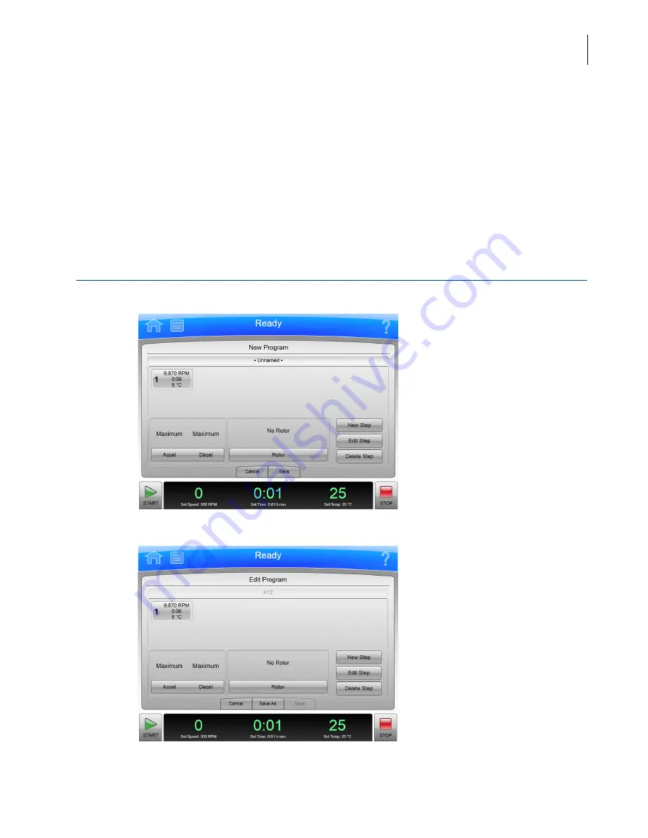
New/Edit/View Program Page

Figure 6.12  

New Program Page 

Figure 6.13  

Edit Program Page 

Summary of Contents for Avanti JXN-26

Page 1: ...PN B38322AA February 2014 User Guide Avanti JXN Series High Performance Centrifuges For In Vitro Diagnostic Use Beckman Coulter Inc 250 S Kraemer Blvd Brea CA 92821 U S A...

Page 2: ...zed logo are trademarks of Beckman Coulter Inc and are registered in the USPTO All other trademarks service marks products or services are trademarks or registered trademarks of their respective holde...

Page 3: ...s to the latest software listed and higher versions When a subsequent software version affects the information in this document a new issue will be released to the Beckman Coulter Web site For labelin...

Page 4: ...PN B38322AA iv Revision History...

Page 5: ...DANGER DANGER indicates an imminently hazardous situation which if not avoided will result in death or serious injury WARNING WARNING indicates a potentially hazardous situation which if not avoided c...

Page 6: ...o your Beckman Coulter Representative Open remove and close replace doors covers and panels with care Use the proper tools when troubleshooting CAUTION System integrity could be compromised and operat...

Page 7: ...w location WARNING Do not place the centrifuge near areas containing flammable or combustible fluids or any other source of vapors that could enter the centrifuge air system and be ignited by the moto...

Page 8: ...your responsibility to decontaminate the instrument and accessories before requesting service by your Beckman Coulter Representative Power Supply DANGER To reduce the risk of electrical shock this in...

Page 9: ...ety DANGER Normal operation may involve the use of solutions and test samples that are pathogenic toxic or radioactive Such materials require that you take all necessary safety precautions Handle body...

Page 10: ...ing on the Avanti JXN series instrument housing These labels and symbols may be associated with user serviceable procedures Individual hazards associated with a specific procedure in this manual may u...

Page 11: ...labelindicates thatthe electronicinformationproductdoesnot containanytoxicorhazardous substances The center e indicates the product is environmentally safe and does not have an Environmentally Friendl...

Page 12: ...ly with Australian Communication Authority ACA EMC Requirements CAUTION This equipment has been designed and tested to CISPR 11 Class A In a domestic environment it could cause radio interference in w...

Page 13: ...a properly earth grounded wrist strap while operating this instrument For details on proper grounding see IEEE standard P1100 DANGER High Voltage Operation replacement or servicing of any components...

Page 14: ...PN B38322AA xiv Safety Notice Summary of Instrument Labels Rotor Rotation This indicates the direction of instrument rotor rotation...

Page 15: ...with Liquids x Volatile Liquids x Summary of Instrument Labels x Caution Symbol x RoHS Notice x China RoHS Caution Label xi China RoHS Environmental Label xi Universal Serial Bus USB xi WEEE Recyclin...

Page 16: ...ure Sensing and Control 1 3 Overtemp System 1 4 Safety Features 1 4 Specifications 1 5 Audible Sounds 1 7 Available Rotors 1 7 CHAPTER 2 The Touch Screen Interface 2 1 Overview 2 1 Areas on the Screen...

Page 17: ...Starting the Run 3 11 Loading the Sample 3 11 Running the Sample 3 12 Unloading the Sample 3 12 Stopping the Run 3 12 Finishing the Run 3 12 CHAPTER 4 Configuration 4 1 Overview 4 1 Managing Your Net...

Page 18: ...6 6 Select Rotor Page Library 6 7 Set Time Page 6 8 Delay Start Page 6 9 Set Speed t Time Page 6 10 Set Temperature Page 6 11 Set Acceleration Deceleration Profiles Page 6 12 Example Acceleration and...

Page 19: ...mage Page 6 39 Set Date and Time Page 6 40 System Log Page 6 41 Manage Rotors Page 6 42 Add to Rotor Library Page 6 43 Diagnostic History Page 6 44 Set Sound Page 6 45 Custom Sounds Page 6 46 Archive...

Page 20: ...Requirements A 1 Single and Three Phase Power Connections A 2 Additional Requirements for Three Phase Power Connections A 4 Space and Location Requirements A 4 Using J2 Series Rotors in the Avanti JX...

Page 21: ...xxi Contents Abbreviations Index Beckman Coulter Inc Avanti JXN Series Centrifuge Warranty Related Documents...

Page 22: ...Page 2 5 2 15 Footer Bar on Other Pages 2 5 2 16 Item Help Button 2 6 2 17 Global Help Button attached to Help Button 2 7 2 18 Home Page Help with ghost image 2 7 2 19 Transparency Button 2 7 2 20 Ho...

Page 23: ...5 2 5 3 Select Program 5 3 5 4 Unnamed program 5 3 5 5 New Program Name 5 4 5 6 Set Acceleration Deceleration Profiles 5 4 5 7 Select Rotor 5 5 5 8 New Step 5 5 5 9 New Step in a numbered sequence 5...

Page 24: ...ter Page 6 27 6 30 Before Run Comment Page 6 28 6 31 Menu Page 6 29 6 32 System Options Page Basic Tab 6 30 6 33 System Options Page System Tab 6 31 6 34 System Options Page Network Tab 6 32 6 35 Syst...

Page 25: ...6 57 6 62 Zonal Operation Page 6 58 7 1 Front View of Vacuum Pump 7 5 7 2 Emergency Door Release Latch Access 7 7 7 3 Manual Door Release 7 8 7 4 Venting the Chamber Vacuum Removing the Red Hose 7 9 7...

Page 26: ...1 2 Available Rotors 1 7 4 1 User Levels 4 5 6 1 Acceleration and Deceleration Profiles 6 13 7 1 Replacement Parts 7 12 A 1 Nominal Supply Voltage Ratings for the Avanti JXN Series A 2 A 2 Required W...

Page 27: ...s It also describes system safety features and centrifuge controls and displays CHAPTER 2 The Touch Screen Interface Describes the touch screen interface for the Avanti JXN series CHAPTER 3 Operations...

Page 28: ...inger on the touch screen to click with a mouse IMPORTANT IMPORTANT is used for statements that add value to a particular step or procedure being performed Following the advice in the IMPORTANT adds b...

Page 29: ...er information incorporated into the Avanti JXN series is protected by internationalcopyright laws Unauthorized copying use distribution transfer orsale is a violation of those laws that may result in...

Page 30: ...PN B38322AA xxx Introduction Symbols Symbols...

Page 31: ...Graphics Graphics All graphics including screens and printouts are for illustration purposes only and must not be used for any other purpose The graphics that your system generates may differ from wha...

Page 32: ...PN B38322AA xxxii Introduction Graphics...

Page 33: ...mperature Sensing and Control Overtemp System Safety Features Specifications Available Rotors For In Vitro Diagnostic Use This Avanti JXN series centrifuge is intended for use as a general purpose lab...

Page 34: ...mple Ficoll Hypaque and Percoll Nucleic acid precipitation Virus isolation Bacteriophage isolation The Avanti JXN series centrifuge design features a brushless switched reluctance drive motor an autom...

Page 35: ...a mechanical rotary vane vacuum pump to reduce chamber pressure The pump turns on after the run is started before rotor friction reaches a high level When the required vacuum level is reached the pum...

Page 36: ...ee Specifications Safety Features Avanti JXN series centrifuges have been designed and tested to operate safely indoors at altitudes up to 2000 m 6562 ft Safety features include the following An elect...

Page 37: ...lapsed time hold run 2t setting range Up to 2 6682 x 1012 radians squared per second Up to 3 5524 x 1012 radians squared per second 2t actual display Indicates accumulated centrifugal effect to five s...

Page 38: ...ady state conditions 5120 Btu h 1 5 kW Humidity restrictions 80 noncondensing Pollution degree 2e HEPA filter Available a Proprietary algorithm applied to provide an estimated sample temperature b To...

Page 39: ...or muted It will play every 5 seconds when the door could be open Available Rotors Refer to the applicable rotor manual for complete rotor descriptions Table 1 2 Available Rotorsa Rotor Profile Descri...

Page 40: ...24 place 45 adapter rmax 116 mm 25 adapter rmax 112 mm 18 000 17 000 18 000 17 000 42 090 36 250 42 090 36 250 24 1 8 mL 24 1 8 mL J TB 037 JA 18 Fixed Angle 23 10 place rmax 132 mm 18 000 18 000 47...

Page 41: ...JLA 10 500 Fixed Angle 20 6 place rmax 166 mm 10 000 10 000 18 590 18 590 6 500 mL J TB 048 F10BCI 6x500y Fixed Angle 23 6 place rmax 158 mm 10 000 10 000 17 700 17 700 6 500 mL JLA 9 1000 Fixed Angle...

Page 42: ...24x5 mL 6x6x5 7 500 7 500 10 400 10 400 4 250 mL J TB 007 JS 5 9 Swinging Bucket 2 place rmax 168 5 mm 5 900 6 570 10 microplates 4deep well plates 2 square well plates J TB 092 JS 5 3 Swinging Bucket...

Page 43: ...adient 39 870 39 870 1900 mL standard zonal a When operating at the maximum speed for the rotor the minimum temperature cannot be selected for all rotors Refer to the specific rotor IFU for details b...

Page 44: ...PN B38322AA 1 12 Description Available Rotors...

Page 45: ...e touch screen interface for the Avanti JXN series Except for the power switch all the controls for the instrument are programmed controls that appear on the touch screen Figure 2 1 Home Page This cha...

Page 46: ...er Bar The Page Display Area Header Bar Figure 2 2 Header Bar The area across the top of the screen is called the Header Bar containing four important items Home Page Button Menu Button Status Display...

Page 47: ...s in the middle of the Header Bar and shows you the current instrument status the current program if selected and programstep ifrunning The Status Displayalso shows when a delayed run is scheduled or...

Page 48: ...lp button gives you access to the built in online help messages Help messages are described at the end of this chapter in Help Messages Footer Bar The bottomof the touch screen always shows the footer...

Page 49: ...is explained below Footer Bar on Other Pages When not on the Home Page the three buttons for Speed Time and Temperature appear in the Footer Bar for easy access To set Acceleration or Deceleration pr...

Page 50: ...age Display Area The Page Display Area is the main display area between the Header Bar and the Footer Bar The pages and help messages all appear in this area The pages are all described in CHAPTER 6 H...

Page 51: ...e Global Help page appears over a ghost image of the screen you were on when you selected global help Figure 2 18 Home Page Help with ghost image If the ghost image makes it difficult for you to read...

Page 52: ...pages You have access to all of the help pages from the Table of Contents Figure 2 21 Help Navigation Buttons To navigate through your selected help pages use the Forward and Back buttons in the upper...

Page 53: ...e Touch Screen Interface About Your Instrument 2 Figure 2 22 About Page Displaying the About Page 1 Select the Menu button on the header bar to display the Menu page 2 Select the About button to displ...

Page 54: ...PN B38322AA 2 10 The Touch Screen Interface About Your Instrument...

Page 55: ...on is a simple procedure you can do from the Home Page Before you begin you must know Which rotor you are using for the run Acceleration and deceleration rate Run speed Length of time for the run Run...

Page 56: ...tart the run Step 1 Start on the Home Page Start at the Home Page If your screen shows any other page select the Home Page Button in the upper left corner of the screen Figure 3 1 Home Page NOTE If yo...

Page 57: ...3 Figure 3 2 Zonal Operation Page with Cancel Button Step 2 Set the Speed and Rotor Select the Set Speed Display Button on the Home Page to go to the Set Speed Page Figure 3 3 Set Speed Page When the...

Page 58: ...he speed inunits of relative centrifugalfield RCF select the RPM RCF Button Note that the RPM RCF button is only enabled when you have selected a rotor 5 Use the keypad to set the desired speed Note t...

Page 59: ...Deceleration Profiles Page On the Set Acceleration Deceleration Profiles Page follow these steps Setting the Acceleration and Deceleration Profiles 1 Select the desired Acceleration and Deceleration...

Page 60: ...hese steps Setting the Time 1 Use the keypad to set the desired time in hours and minutes Use the Back and Clear keys to make corrections You can also use the Hold key to set the time to a hold state...

Page 61: ...stop time Select Delay Start to display the Delay Start Page Figure 3 7 Delay Start Page Select Start At or Stop At to set a starting or stopping time Then you can set the date and time in the fields...

Page 62: ...in degrees Celsius Use the Back and Clear keys to make corrections 2 Select the OK key to accept your entry and dismiss the page Step 6 Start the Run Once the run values are set start the run NOTE If...

Page 63: ...ed and qualified Guard against accidentally dropping objects such as pens pencils or hemostats into the chamber Loose lab coats neckties scarves and long necklaces should not be worn while operating i...

Page 64: ...Flow run Preparing Starting Loading Running Unloading Stopping Finishing Each phase is outlined in a section below Preparing for the Run The rotor manual details the preparations for a run which may i...

Page 65: ...o Zero RPM button will bring the rotor to a stop but the instrument will remain in Zonal mode Refer to Figure 3 11 When the rotor passes the alignment and adjustment checks set the new loading speed i...

Page 66: ...the instrument will slow the rotor to the Load Speed The instrument will remain in the Loading phase until you select the To Running button to return to the Running phase or terminate the run Unloadi...

Page 67: ...transfer and printing to a network printer You can also enable VNC Virtual Network Computing or API Application Programming Interface to allow the system to receive instructions from a remote applica...

Page 68: ...inter for the instrument The system automatically sends all print requests to the selected printer NOTE Printer drivers must be installed by your Beckman Coulter Representative 1 Select the Menu Butto...

Page 69: ...ons sent by the instrument You can change the default to a legitimate or fictitious address depending on your requirements Select the field to enter the new address then select OK to save the address...

Page 70: ...lect Back to return to the System Options page Enabling API Use this option to allow a remote device to connect to the instrument using the API 1 Select the Menu Button on the Header Bar to display th...

Page 71: ...d 8 Select the User Level For Operators you can select the Authorize Programs button to add programs to the User See Creating Programs in CHAPTER 5 Programs for more information 9 Select Save to add t...

Page 72: ...ation and Logout Timer 1 Select the Menu Button on the Header Bar to display the Menu Page 2 Select Options to display the System Options Page 3 Select the Users Tab 4 To change the PIN expiration sel...

Page 73: ...ve to change the PIN and return to the User Options Page 5 To add or change the email or phone number select the Email or Phone field to display the Edit Email or Edit Phone page Use the keypad to upd...

Page 74: ...ct a type of rotor from the list on the left 6 You must enter a serial number for the rotor Select the Serial Number field to display the Serial Number Page Enter the serial number and select OK to re...

Page 75: ...e Acceleration and Deceleration parameters Before Run Comment After Run Comment Detailed information about each step in a run Graph of the run Electronic signature if applicable User Access An Operato...

Page 76: ...r print it 1 On the Home page select the Run History button on the side menu Figure 4 2 Run History Button 2 On the Run History page select the Filter tab at the bottom of the screen 3 On the Run Hist...

Page 77: ...e andAM PM Thenselect OK to returnto the Run History Filter page 6 Select the To button under Filter by Date 7 On the Set To Date and Time page again use the up and down arrow buttons to set the param...

Page 78: ...he Run Graph Options page select one of three options under Run Graph View Scope Fit To Screen Auto Scroll or Manual Scroll The default is Fit To Screen Then select OK Graphing Data for a Previously C...

Page 79: ...Run Graph page or the Run History page NOTE You must have Administrator access to configure the printer Printing Run History from the Run Graph Page 1 After the run is completed select the Run Graph b...

Page 80: ...history for all currently listed runs to the printer configured by the Administrator Export Data Run history data can be manually exported to an external media source such as a USB drive or automatic...

Page 81: ...Drives list and select the Export button The Avanti JXN series will then export the currently listed run histories to the USB drive Manually Exporting Run History Data to a Mapped Network IMPORTANT B...

Page 82: ...have write permission to a folder where the automatically exported run history data can be stored Enabling Auto Print 1 Select the Menu button on the Header Bar to display the Menu page 2 Select the O...

Page 83: ...nction follow the previous four steps The small box in the Auto Export button will turn grey to indicate it is disabled Enabling Run Comments The Run Comments function enables the user to add comments...

Page 84: ...age Enter a comment and select OK The comments appear in the Summary tab of the Run History page E Signature The E Signature function permits a user to electronically add a signature and add a note if...

Page 85: ...4 In the Sign As box select Author Reviewer or Approver NOTE You can select the Author option only if you started the run You must have Super User or Administrator access to select Reviewer or Approve...

Page 86: ...PN B38322AA 4 20 Configuration Managing Reports The note and E Signature will be added to the Summary on the Run History page See the Run History Page for more information...

Page 87: ...create and store programs in the centrifuge memory A program is a series of steps containing parameters for a run Programs are retained in the centrifuge memory until they are deleted This chapter co...

Page 88: ...ograms Creating Programs Creating Programs 1 Select Program from the side menu on the Home page NOTE When Require Login is enabled programs can only be created by an Administrator or Super User Figure...

Page 89: ...ing Programs 5 2 On the Select Program page select the New button Figure 5 3 Select Program 3 On the New Program page Unnamed appears as the title To name the new program now select Unnamed on the scr...

Page 90: ...ogram names cannot be reused Figure 5 5 New Program Name 5 On the New Program page select the Accel Decel buttonto set the Acceleration and Deceleration profiles On the Acceleration Deceleration Profi...

Page 91: ...aking your selection select OK to save themand return to the previous page NOTE Specifying a rotor type is optional However if a rotor type is selected within the program editor this constrains the ot...

Page 92: ...be between 1 minute and 99 hours 59 minutes c Select the Set Temp button then use the keypad to set the temperature d When the parameters for Speed Time and Temperature are set select OK to save the...

Page 93: ...e Super User or Administrator access to change a run in progress If you select the Set Speed Set Time or Set Temp buttons to change the parameters while a program is running the system displays a mess...

Page 94: ...K to save the changes and return to the previous page 5 On the Edit Program page you can select the Accel Decel button and or the Rotor button and modify each set of parameters Then select Save Deleti...

Page 95: ...ime Page Delay Start Page Set Speed t Time Page Set Temperature Page Set Acceleration Deceleration Profiles Page Login Page Select Program Page New Edit View Program Page Select Rotor Page Catalog New...

Page 96: ...nd Time Page System Log Page Manage Rotors Page Add to Rotor Library Page Diagnostic History Page Set Sound Page Custom Sounds Page Archive Data Page Setup Network Page Select Printer Page Setup Email...

Page 97: ...Set Speed Display Button shows the current rotor speed as a large number and also shows the current run speed setting in small characters across the bottom Select the Set Speed Display Button to displ...

Page 98: ...must be accessed from the Home page and includes the following buttons If your system requires login the Login Logout button Select this button to log in or out of the system The Program button Select...

Page 99: ...ed Display shows the actual speed of the rotor in RPM or RCF The Set Time Display shows the time remaining in the run or the present step of the run program If the time setting is Hold it displays the...

Page 100: ...m displays the Set Speed t Time Page In addition to the Header Bar and the Footer Bar the Set Speed page contains the following elements The Set Speed Display at the top of the page shows the current...

Page 101: ...page This page displays the library of rotors that have been entered for your instrument In addition to the Header Bar and the Footer Bar the Select Rotor page contains the following elements The Rot...

Page 102: ...nd minutes The keypad changes the time setting You can use the Clear and Back keys to make corrections The Hold key sets the time to a hold state with no countdown to an automatic end When you select...

Page 103: ...r the run The No Delay button default sets the run start time to the present and disables the Date Time scroll arrows The Start At button enables the Date Time scroll arrows and sets the run to start...

Page 104: ...last to reflect the new speed value The Set t Display Button shows the current t value Select this button to set a new t value The time then changes to reflect the new t value The Set Time Display But...

Page 105: ...r Bar to display the Set Temperature page In addition to the Header Bar and the Footer Bar the Set Temperature page contains the following elements The Set Temperature Display shows the current Set Te...

Page 106: ...es and dismisses the page The OK button accepts your changes and dismisses the page The acceleration values are the degree of reduction from the maximum value The acceleration value of zero is the max...

Page 107: ...and JS 24 15 rotors Full torque is used from 0 RPM until set speed is reached Timed acceleration Acceleration time from 0 to 500 RPM can be set from 1 to 10 minutes Above 500 RPM full torque is used u...

Page 108: ...y only view and run programs In addition to the Header Bar and the Footer Bar the Select Program page contains the following elements Select a program from the list on the left to run edit view delete...

Page 109: ...changes and dismiss the page Select Print to print the selected program Select Export to export the selected program The system displays the Export Page Select Import to import a program The system d...

Page 110: ...steps appear in the Step List Acceleration and Deceleration Profiles appear in the Accel Decel area Select the Accel Decel button to display the Set Acceleration Deceleration Profiles Page to select...

Page 111: ...eries In addition to the Header Bar and the Footer Bar the Select Rotor page contains the following elements The Rotor Catalog List shows the rotors that can be used with the instrument Select a rotor...

Page 112: ...he New Program Page or the Edit Program Page to display the Edit Step page The pages contain the same options In addition to the Header Bar and the Footer Bar the New Edit Step page contains the follo...

Page 113: ...Program Log Page To display the history of changes to a run program select the program and select the Program Log button on the Select Program Page to display the Program Log page for the selected pr...

Page 114: ...r NOTE Do not remove a USB drive while a data transfer is in progress In addition to the Header Bar and the Footer Bar the Export page contains the following elements The Export Item at the top tells...

Page 115: ...rs page contains the following elements The program name appears at the top of the page The list box displays the Operator level users in the system Users with permission to run the program are highli...

Page 116: ...page contains the following elements The Import Item at the top tells you what you are about to import images programs custom sound files The Available Drives list shows all the available network and...

Page 117: ...Run Data Historical Run Data Page Figure 6 22 Real Time Run Data Page Figure 6 23 Historical Run Data Page Select the Run Graph button on the side menu of the Home Page to display the Real Time Run Da...

Page 118: ...the Run Graph Options page The Print button prints the graph Run Graph Options Page Figure 6 25 Run Graph Options Page Select the Options button on the Real Time Run Data Historical Run Data Page to...

Page 119: ...0 minutes of the run with a scroll bar beneath the run graph to scroll through the entire run Select the Cancel button to discard your changes and return to the previous page Select the OK button to a...

Page 120: ...e enabled see The Reports Tab use the Signature tab to sign off on the run as the Author Reviewer or Approver You must select a role to enable the Add Note and Sign buttons Active options are determin...

Page 121: ...y Filter page Use this page to narrow the parameters for the run logs that will be displayed printed or exported on the Run History Page In addition to the Header Bar and the Footer Bar the Run Histor...

Page 122: ...he Reports Tab it displays the Before Run Comment page when you start a run and the After Run Comment page when a run ends In addition to the Header Bar and the Footer Bar the Run Comment pages contai...

Page 123: ...Options button displays the System Options Page The Rotor Catalog button displays the Rotor Catalog Page The About button displays the About Page The Zonal Operation button displays the Zonal Authori...

Page 124: ...he following elements organized on five tabs The Basic Tab The Select Language button displays the Select Language Page The User Options button displays the User Options Page The t Mode button enables...

Page 125: ...the System Options page The Set Date and Time button displays the Set Date and Time Page The System Log button displays the System Log Page The Manage Rotors button displays the Manage Rotors Page The...

Page 126: ...he Setup Network Page The Select Printer button displays the Select Printer Page The Setup Email button displays the Setup Email Page The Setup VNC button displays the Setup VNC Page The Enable API bu...

Page 127: ...To disable PIN Expiration enter 0 and select OK to return to the System Options Page NOTE The PIN Expiration Page allows you to configure the amount of time before the PIN expires The Require Login b...

Page 128: ...rint and Auto Export Run History Data for more information The Email on End Run button enables and disables sending an automatic email at the conclusion of each run If your system is configured for em...

Page 129: ...ing elements The List of Languages shows all the languages and countries available for the instrument Scroll through this list and select a language and country The Cancel button discards your selecti...

Page 130: ...your system is configured for email it will send all diagnostic messages to the address you enter If enabled it will also send an end of run notification to the user that initiated the run Select Sav...

Page 131: ...pecify whether the run should shut down or continue if the overtemp setting is reached by using the Max Temperature Shutdown button on the Basic tab of the System Options Page In addition to the Heade...

Page 132: ...your User ID In addition to the Header Bar and the Footer Bar the Reset User PIN page contains the following elements Enter your current PIN in the Enter PIN field Enter your new PIN in the Enter new...

Page 133: ...Select Image Page Avatar Figure 6 42 Select Image Page Background Select the Set Avatar button or the Set Background button on the User Options Page to display the Select Image page Use this page to...

Page 134: ...50 KB for Background Image and 20 KB for Avatar Set Date and Time Page Figure 6 43 Set Date and Time Page Select the Set Date and Time button on System tab of the System Options Page to display the S...

Page 135: ...s to the system select the System Log button on the System tab of the System Options Page to display the System Log page In addition to the Header Bar and the Footer Bar the System Log page contains t...

Page 136: ...tors for more information In addition to the Header Bar and the Footer Bar the Manage Rotors page contains the following elements The rotor list displays the rotors that have been added to the library...

Page 137: ...the left lists all the rotors that are compatible with the instrument Select the type of rotor to add to the library Select the Serial Number field to display the Enter Serial Number page Enter the r...

Page 138: ...tion to the Header Bar and the Footer Bar the Diagnostic History page contains the following elements The List of Events on the left side of the screen shows all the diagnostic events for the instrume...

Page 139: ...key click option In addition to the Header Bar and the Footer Bar the Set Sound page contains the following elements The Volume buttons determines one of the four system volumes Mute silent Low Mediu...

Page 140: ...tom Sounds page contains the following elements The system sound list shows the system events with audible notices Select an event to review or change the associated sound Select Import to import a so...

Page 141: ...e imported back into the system The Programs button enables and disables run program export The Run History button enables and disables export of run logs The Diagnostic History button enables and dis...

Page 142: ...ield to display the Network Path page and enter the base network path for import and export This should be a UNC path e g server sharename folder Select OK to return to the Setup Network page DHCP Mod...

Page 143: ...Footer Bar the Select Printer page contains the following elements The Printer list shows the configured printers on the network or physically connected to the instrument Printers must be configured...

Page 144: ...may be required by your email server Select the fields to enter the required values then select OK to return to the Setup Email page Email From defines the return email address that appears on email n...

Page 145: ...from a laptop or other remote device The Enable or Disable VNC Server Enable button enables or disables the VNC server The Synchronize VNC Password To Logged in User PIN Enable button enables or disa...

Page 146: ...dit User Page Select a User ID and select Delete to remove a user profile from the list The system displays a confirmation message Select Yes to remove the user profile User IDs cannot be re used Sele...

Page 147: ...D cannot be changed Select the PIN field to set or change the PIN Enter the new PIN in the Enter PIN field and repeat the same number in the Confirm PIN field Select OK to return to the Add Edit User...

Page 148: ...ograms button on the Add Edit User Page to display the Authorize Programs page In addition to the Header Bar and the Footer Bar the Authorize Programs page contains The User ID appears at the top of t...

Page 149: ...r all the rotors compatible with the Avanti JXN series In addition to the Header Bar and the Footer Bar the Rotor Catalog page contains the following elements The rotor list on the left side of the sc...

Page 150: ...ect the About button on the Home Page This page presents system information about your instrument In addition to the Header Bar and the Footer Bar the About page contains the following operating eleme...

Page 151: ...Page to display the Zonal Authorization page Enter the authorization code 1793 and select Authorize to use Zonal mode for the next run Figure 6 61 Zonal Mode Button In addition to the Header Bar and...

Page 152: ...r additional details As a display the Load Speed Display Button shows the sample loading speed Use the arrow buttons above and below to increase or decrease the sample loading speed or select the butt...

Page 153: ...cel and Decel Display Button shows the currently selected acceleration or deceleration profile Select the button to display the Set Acceleration Deceleration Profiles Page The Cancel button ends Zonal...

Page 154: ...PN B38322AA 6 60 Functional Pages Zonal Operation Page...

Page 155: ...and Transportation Supply List Field Service For any maintenance not covered in this manual contact your Beckman Coulter Representative for assistance USA customers can call 1 800 742 2345 For interna...

Page 156: ...djusted as appropriate for your laboratory conditions b Make sure that the chamber chamber gasket and door are dry before each run NOTE Before using any cleaning or decontamination methods except thos...

Page 157: ...azardous contamination and or operator injury Be careful when examining or cleaning the chamber and chamber gasket as sharp glass fragments may be embedded in their surfaces 2 Examine the chamber gask...

Page 158: ...nol is a flammability hazard Do not use it in or near operating centrifuges Ethanol 70 may be used to clean any exterior surface of the centrifuge While Beckman Coulter has tested ethanol 70 and found...

Page 159: ...ding the filter by the side edges insert the top half behind the frame edge and lift up until the bottom half clears the retaining strip c Then set the bottom edge down Checking the Vacuum Pump IMPORT...

Page 160: ...ctions and their corrective actions see APPENDIX C Diagnostics Accessing the Rotor in Case of Power Failure WARNING Any maintenance procedure requiring removal of a panel exposes the operator to the p...

Page 161: ...ain source by removing the Mains power plug from the outlet receptacle The Mains power plug is the disconnect device and must remain easily accessible Position the centrifuge so that it is easy to rem...

Page 162: ...d while holding it out step on the foot pedal Depending on the level of vacuumin the chamber at the time of the power failure the door may or may not open a If it opens go to step 6 b If it does not o...

Page 163: ...ver these lines Make sure that they stay connected as you pull CAUTION Risk of instrument damage Do not twist the hose to the left counterclockwise as you pull the hose or you will unscrew the hose fi...

Page 164: ...ore attempting to access the sample 10 Remove your sample Replacing the Front Panel on the Centrifuge 1 Holding the panel at the top with the instrument label facing out insert the three grooved brack...

Page 165: ...5000 RPM and back to 0 RPM three times This procedure will distribute lubricant around the bearings in the rotating seal assembly reducing drag 2 In older JCF Z rotors with bearings that have not bee...

Page 166: ...Zonal Bracket qty 1 363818 Thumbscrew stainless steel M4 threads X 19 mm qty 2 893412 Thumbscrew stainless steel M4 threads X 12 mm qty 2 893411 Cable Clamp nylon 6 4 mm 1 4 in I D qty 10 000499 Avant...

Page 167: ...ce and Troubleshooting Supply List 7 Cable Clamp nylon 9 6 mm 3 8 in I D qty 10 000596 External HEPA Filter Assembly NOTE Accessory HEPA filter Kit B37916 is required B45269 Table 7 1 Replacement Part...

Page 168: ...PN B38322AA 7 14 Maintenance and Troubleshooting Supply List...

Page 169: ...ltmeter For single phase centrifuges two 30 ampere circuit breakers For three phase centrifuges three 16 ampere circuit breakers Power receptacle see Figure A 1 or Figure A 2 Electrical Requirements P...

Page 170: ...ngle and Three Phase Power Connections Figure A 1 shows the power connection for single phase centrifuges including earth ground and two power leads with 30 ampere circuit breakers Figure A 2 shows th...

Page 171: ...0 Bryant 96 30 FR or Equivalent NEMA 6 30 R 3 Earth Ground 4 Measured Line Voltage 1 16 ampere Circuit Breaker 2 Neutral 3 Measured Line Voltage Phase to Phase 4 Earth Ground Table A 2 Required Wire C...

Page 172: ...entrifuge must be of sufficient wire gauge to provide this condition The wire gauge required at a particular site must be determined by a facilities engineer at that site Figure A 3 Correct and Incorr...

Page 173: ...J2 Series Rotors in the Avanti JXN Series CAUTION Do not use the Beckman Coulter JA 10 JS 7 5 or JA 14 rotors in the Avanti JXN centrifuge before reading this information Checking for Rotor Drive Pin...

Page 174: ...i JXN series centrifuge and do not use rotors without drive pins in the Avanti JXN series To check for drive pins hold the rotor up or turn it on its side and look into the drive hole If you do not se...

Page 175: ...hardware and assembly instructions This kit is for use with Cole Parmer tubing size 16 6 4 mm 1 4 in O D the tubing size most commonly used with the JCF Z rotor Two additional kits are available one w...

Page 176: ...PN B38322AA A 8 Preinstallation Requirements Using J2 Series Rotors in the Avanti JXN Series...

Page 177: ...st samples to the required temperature The length of precooling prewarming time depends on how different the rotor starting temperature is from the required run temperature 2 Install the rotor with ad...

Page 178: ...nd set temperatures are different note how many degrees different they are and adjust the set temperature up or down that number of degrees For example If the required sample temperature is And the me...

Page 179: ...ce by your Beckman Coulter Representative Diagnostics User Messages Chart Refer to the chart below for a list of possible malfunctions and their corrective actions Table C 1 Diagnostics User Messages...

Page 180: ...s 90 full Backup files soon Contact your Beckman Coulter Representative S127 Internal software error Calibration parameters lost Contact your Beckman Coulter Representative S128 Door lockout active Un...

Page 181: ...your Beckman Coulter Representative R3 Rotor mismatch Run stops using maximum brake Insure rotor installed matches rotor entered on user interface If error persists contact your Beckman Coulter Repres...

Page 182: ...an Coulter Representative C2 C3 C5 Temperature control error Run stops using maximum brake Contact your Beckman Coulter Representative F1 F3 F11 Vacuum error Run stops using maximum brake Contact your...

Page 183: ...ornedControl the recipient accepts and agrees to be bound by the terms of CPOL B PasswordAssistant available at http blog functionalfun net 2008 06 wpf passwordbox and data binding html and ListBoxSel...

Page 184: ...right patent trademark and attribution notices that are present in the software d If you distribute any portion of the software in source code form you may do so only under this license by including a...

Page 185: ...ng you legal permission to copy distribute and or modify it For the developers and authors protection the GPL clearly explains that there is no warranty for this free software For both users and autho...

Page 186: ...means the preferred form of the work for making modifications to it Object code means any non source form of a work A Standard Interface means an interface that either is anofficial standard defined b...

Page 187: ...PO copyright treaty adopted on 20 December 1996 or similar laws prohibiting or restricting circumvention of such measures When your convey a covered work you waive any legal power to forbid circumvent...

Page 188: ...hree years and valid for as long as you offer spare parts or customer support for that product model to give anyone who possesses the object code either 1 a copy of the Corresponding Source for all th...

Page 189: ...nied by the Installation Information But this requirement does not apply if neither you nor any third party retains the ability to install modified object code on the User Product for example the work...

Page 190: ...nsing or conveying under this License you may add to a covered work material governed by the terms of that license document provided that the further restriction does not survive such relicensing or c...

Page 191: ...ed under this License and you may not initiate litigation including a cross claim or counterclaim in a lawsuit alleging that any patent claim is infringed by making using selling offering for sale or...

Page 192: ...e or other defenses to infringement that may otherwise be available to you under applicable patent law 12 No Surrender of Others Freedom If conditions are imposed on you whether by court order agreeme...

Page 193: ...M IS WITH YOU SHOULD THE PROGRAM PROVE DEFECTIVE YOU ASSUME THE COST OF ALL NECESSARY SERVICING REPAIR OR CORRECTION 16 Limitation of Liability IN NO EVENT UNLESS REQUIRED BY APPLICABLE LAW OR AGREED...

Page 194: ...PN B38322AA D 12 Third Party Contributions and Legal Notices Contributions and Legal Notices...

Page 195: ...ernal HEPA filter is located on the left side of the centrifuge To replace the filter assembly remove the tubing from the plastic barbed fitting protruding from the side of the centrifuge Install the...

Page 196: ...PN B38322AA E 2 HEPA Filter Replacement Instructions for the Avanti JXN Series Centrifuges HEPA Filter Replacement...

Page 197: ...Efficiency Particulate Air Hr Hour Hz Hertz ID Identification in Inches IP Internet Protocol IEEE Institute of Electrical and Electronics Engineers ISO International Organization for Standardization I...

Page 198: ...PN B38322AA Abbreviations 2 Abbreviations...

Page 199: ...ng 7 4 alerts safety v API defined Abbreviations 1 to enable 4 4 archive data page 6 47 areas on the screen 2 2 accel and decel display button 2 6 footer bar 2 4 footer bar on other pages 2 5 footer b...

Page 200: ...graphics xxxi display about page 2 9 DNS defined Abbreviations 1 door release emergency latch access 7 7 manual 7 8 DRIC defined Abbreviations 1 drive 1 3 E editing programs 5 7 EFUP defined Abbreviat...

Page 201: ...x intended use for in vitro diagnostic use 1 1 IVD 1 1 IP defined Abbreviations 1 ISO defined Abbreviations 1 IVD defined Abbreviations 1 J JCF Z rotor identification 7 11 JCF Z continuous flow zonal...

Page 202: ...sounds 6 46 delay start 3 7 6 9 diagnostic history 6 44 export 6 20 home 2 1 3 2 6 3 home run in progress 6 5 home page 5 2 import 6 22 login 6 13 manage users 6 52 menu 6 29 new program name 5 4 new...

Page 203: ...gin 4 5 reset user PIN page 6 38 rotor catalog page 6 55 rotor chamber 1 3 rotor identification JCF Z 7 11 rotors adding 4 8 RPM defined Abbreviations 1 run comments enable 4 17 use 4 17 run graph opt...

Page 204: ...symbols xxx system overtemp 1 4 system log page 6 41 system options page 6 30 system tab 6 31 T tab basic 6 30 network 6 32 system 6 31 users 6 33 temperature calibration B 1 temperature control 1 3...

Page 205: ...eration page 6 58 zonal or continuous flow run seven phases 3 10 zonal or continuous flow run seven phases finishing 3 10 3 12 loading 3 10 3 11 preparing 3 10 running 3 10 3 12 starting 3 10 3 11 sto...

Page 206: ...Index 8 Index...

Page 207: ...paid and will be returned to Buyer with the transportation charges collect unless the product is found to be defective in which case Beckman Coulter will pay all transportation charges Beckman Coulter...

Page 208: ...PN B38322AA Warranty 2 Beckman Coulter Inc Avanti JXN Series Centrifuge Warranty...

Page 209: ......

Page 210: ...pe Rotors Care and Maintenance Chemical Resistances Temperature Compensation Tables Gradient Materials Available in electronic pdf or CD ROM by request Chemical Resistances for Beckman Coulter Centrif...

Reviews: