background image

Mounting and wiring

KL8001 and KL9060

20

Version: 2.0.0

3.4

Application examples

WARNING

Protection of the load circuit

Ensure that the load circuit can be fused with up to a maximum of 25 A per phase.

Motor control

The following figure illustrates control of a three-phase AC motor utilizing a KL8001 and a Siemens
contactor. The power terminal's Out1 output controls the Siemens contactor.

Fig. 9: Application example: Motor control

Reversing contactor connection

The following figure illustrates a reversing contactor connection utilizing a KL8001 and two Siemens
contactors. The power terminal's Out1 and Out2 outputs alternately control the two Siemens contactors.

Summary of Contents for KL8001

Page 1: ...Documentation KL8001 and KL9060 Power terminal for Siemens contactors of the Sirius 3RT10 series 2 0 0 2017 09 15 Version Date...

Page 2: ......

Page 3: ...and wiring 15 3 1 Installation on mounting rails 15 3 2 Mounting the KL8001 18 3 3 Connection 19 3 4 Application examples 20 4 KS2000 Configuration Software 22 4 1 KS2000 Introduction 22 4 2 Parameter...

Page 4: ...Table of contents KL8001 and KL9060 4 Version 2 0 0...

Page 5: ...of the data diagrams and descriptions in this documentation Trademarks Beckhoff TwinCAT EtherCAT Safety over EtherCAT TwinSAFE XFC and XTS are registered trademarks of and licensed by Beckhoff Automa...

Page 6: ...re familiar with the applicable national standards Description of symbols In this documentation the following symbols are used with an accompanying safety instruction or note The safety instructions m...

Page 7: ...plication examples added Description of parameterization with KS2000 software added Description of the process image revised Register description amended Ordering information added 0 1 First prelimina...

Page 8: ...tax of the serial number for KL8001 Structure of the serial number KK YY FH fh KK week of production CW calendar week YY year of production FH firmware version F and hardware version H of the measurin...

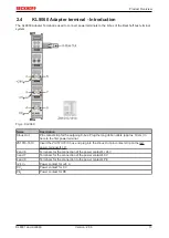
Page 9: ...ded with the KL9060 in the last power terminal of your bus terminal block L1 L2 L3 Connection terminals for the load circuit from the mains L1 L2 L3 Connection pins for the load circuit to the contact...

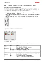
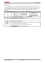
Page 10: ...y switches Fig 2 KL8001 rotary switch for setting the rated current LEDs Fig 3 KL8001 LEDs The power terminal has 4 LEDs for status display to enable rapid diagnosis The possible states are listed in...

Page 11: ...1 0 No rated current set both the two rotary switches and the register PR33 are zero single phase analysis 26 not active or at least one of registers PR33 PR39 or PR45 is zero single phase analysis i...

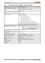
Page 12: ...nce Measuring voltage 500 V Type of K bus connection 2 x flat plug socket 10 pin K bus current consumption 5 VDC typically 150 mA Observe the maximum current 14 that your Bus Coupler can supply to the...

Page 13: ...oing K bus Plug the long ribbon cable approx 10 cm in here to the first power terminal ZS1010 1610 Insert the ZS1010 1610 bus end plug into the K bus Out pin contact strip on the last power terminal 1...

Page 14: ...current consumption of your terminals exceeds the maximum current that your Bus Coupler can feed to the K bus supply Number of power terminals per KL9060 10 max If you operate two contactors with each...

Page 15: ...the Fieldbus Coupler Join the compo nents with tongue and groove and push the terminals against the mounting rail until the lock clicks onto the mounting rail If the Terminals are clipped onto the mou...

Page 16: ...ponents The six spring contacts of the K Bus E Bus deal with the transfer of the data and the supply of the Bus Terminal electronics The power contacts deal with the supply for the field electronics a...

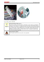
Page 17: ...ation testing or to damage on the terminal e g disruptive discharge to the PE line during insulation testing of a consumer with a nominal voltage of 230 V For insulation testing disconnect the PE supp...

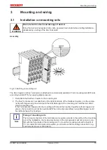
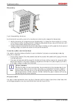
Page 18: ...s size S00 as listed in the ordering information 45 Installing a Bus Terminal block with power terminals When mounting observe the information in the chapter entitled Mounting rail installation 15 1 E...

Page 19: ...sing a ribbon cable about 3 cm Insert the ZS1010 1610 bus end plug included with the KL9060 into the last power terminal Fig 8 KL8001 KL9060 Connection Power is supplied to the KL8001 electronics via...

Page 20: ...gure illustrates control of a three phase AC motor utilizing a KL8001 and a Siemens contactor The power terminal s Out1 output controls the Siemens contactor Fig 9 Application example Motor control Re...

Page 21: ...contactor connection directly at the contactor see dia gram below To do this remove the connections for the auxiliary contacts and for A1 at the mains side bridge of the Siemens kit by breaking these...

Page 22: ...eldbus Box Modules can be prepared before the commissioning phase Later on this configuration can be transferred to the terminal station in the commissioning phase by means of a download For documenta...

Page 23: ...ssioning of the output modules All possibilities in the online mode can be used in parallel with the actual fieldbus mode of the terminal station The fieldbus protocol always has the higher priority i...

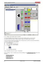
Page 24: ...ndow contains a graphic display of the fieldbus station terminals In the tree structure of the left hand window click on the plus sign next to the terminal whose parameters you wish to change item 2 i...

Page 25: ...ion of the terminal in the terminal block Type Terminal type Channel Channel whose parameters are displayed in the configuration screen Firmware Firmware version of the K bus PCB Configuration screen...

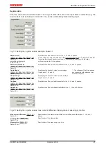
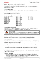
Page 26: ...is off then the values entered for phase L1 applies to all three phases Read rotary switches permanently PR32 5 34 Default active In normal operation the rotary switches 10 for setting the rated curre...

Page 27: ...threshold for the L1 L2 and L3 phases Overvoltage PR35 35 PR41 35 PR47 36 Default 350 V Specifying the threshold value for overvoltage for phases L1 L2 and L3 The voltages of the three phases are meas...

Page 28: ...trol Byte ECB 30 10 14 Word not used not used Word Alignment The Bus Coupler places values on even byte addresses The process image is extended by an unused word in the input and output range so that...

Page 29: ...Error Info DR no Key Bit Name Description SB0 7 RegAccess 0bin Acknowledgement for process data access SB0 6 ES Error Info 1bin The lowest nibble ES 3 to ES 0 in the extended status byte 31 contains...

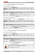
Page 30: ...h on the contactor mounted directly on the power terminal ECB 4 to ECB 1 0bin reserved ECB 0 Clear Imax 1bin The DR2 41 data registers are set to zero in all three register sets they con tain the peak...

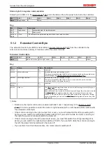
Page 31: ...error information Evaluate the status word ESB 2 Overload motor STOP 1bin The power terminal has switched off the motor because the current integral data register DR7 41 has reached the maximum value...

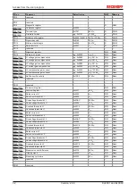
Page 32: ...served PR30 reserved PR31 33 Code word register R W RAM PR32 34 Feature Register 0x0221 545dec R W Flash PR33 34 Rated current L1 0x0000 0dec R W Flash PR34 35 Switch on threshold L1 0x0000 0dec R W F...

Page 33: ...G Risk of injury During a software reset the contactor connected to the power terminal is released Ensure that your system state permits this and that hazards for persons or machinery have been ruled...

Page 34: ...ic is active 0bin PR32 7 0bin reserved 0bin PR32 6 0bin reserved 0bin PR32 5 enPermanent RotarySwitchEvaluation 0bin The rotary switches for the rated current are only read during a power re set 1bin...

Page 35: ...a resolution of 0 1 V in register PR36 bit SW 4 will be set in the status word 42 The voltages of the three phases are measured with reference to an artificial star point PR37 Overload threshold L1 I...

Page 36: ...d stored with a resolution of 0 1 V in register PR47 bit SW 9 will be set in the status word 42 The voltages of the three phases are measured with reference to an artificial star point PR48 L3 undervo...

Page 37: ...ister Communication The numbering of the bytes in the examples corresponds to the display without word alignment 5 2 2 1 Example 1 reading the firmware version from Register 9 Output Data Byte 0 Contr...

Page 38: ...tion Input Data answer of the bus terminal Byte 0 Status byte Byte 1 DataIN1 high byte Byte 2 DataIN1 low byte 0x9F 1001 1111bin 0xXX 0xXX Explanation The terminal returns a value as a receipt in the...

Page 39: ...m the Bus Terminal Byte 0 Status byte Byte 1 DataIN1 high byte Byte 2 DataIN1 low byte 0xA0 1010 0000bin 0xXX 0xXX Explanation The terminal returns a value as a receipt in the status byte that differs...

Page 40: ...0 0 specify the register number 31 with 01 1111bin The output data word byte 1 and byte 2 contains 0x0000 for reactivating write protection Input Data answer of the bus terminal Byte 0 Status byte Byt...

Page 41: ...consumption 3 L3 1 kWh DR9 Energy consumption sum of 3 phases 1 kWh Maximum current difference be tween L1 L2 and L3 0 01 A Cos phi mean value of L1 L2 and L3 0 01 DR10 Rated current set at the rotar...

Page 42: ...W 6 SW 5 SW 4 SW 3 SW 2 SW 1 SW 0 Key Bit Name Value Description SW 15 Other errors 1bin another error has occurred SW 14 No rated current set 1bin Both the two rotary switches and register PR33 34 is...

Page 43: ...minal menu item Insert a power terminal The KL8001 is found in the Power Terminals KL800x group You can insert up to 10 power terminals at the end of the terminal block with the KL9060 Adapter Termina...

Page 44: ...ation System is a continuously growing reference system for TwinCAT products It contains technical information manuals sample code the BECKHOFF Knowledge Base and much more The setup for installing th...

Page 45: ...o power terminals with a reversing contactor connection ZK1010 8080 3010 1 x long approx 10 cm ribbon cable for the bus connection between the adapter terminal and the first power terminal or KS2000 1...

Page 46: ...components there Beckhoff Headquarters Beckhoff Automation GmbH Co KG Huelshorstweg 20 33415 Verl Germany Phone 49 0 5246 963 0 Fax 49 0 5246 963 198 e mail info beckhoff com Beckhoff Support Support...

Page 47: ...kit for reversing combination 21 Fig 12 KS2000 configuration software 22 Fig 13 Display of the fieldbus station in KS2000 24 Fig 14 KS2000 branches for channel 1 of the KL8001 24 Fig 15 Settings via...

Reviews: