Mounting and wiring
KL2532/KS2532, KL2552/KS2552
33
Version: 3.2.0
4.8
KL2552-0000/KS2552-0000 - connection
WARNING
Risk of injury through electric shock and damage to the device!
Bring the Bus Terminals system into a safe, de-energized state before starting mounting, disassembly or
wiring of the Bus Terminals.
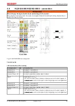
Fig. 20: KL2552/KS2552 pin assignment
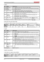
Terminal points
Left-hand section of the housing
Terminal point
No.
Connection for
Encoder A, A
1
Encoder A, connection A
Encoder B, A
2
Encoder B, connection A
Encoder Power +24
V
3
Encoder supply (from positive power contact)
Input 1
4
Digital input 1 (24 V
DC
).
The current counter value is stored as reference mark in the latch register, if
bit
is set in control byte 1 and a rising edge occurs at digital input
1.
Encoder A, B
5
Encoder A, connection B
Encoder B, B
6
Encoder B, connection B
Encoder Power 0 V
7
Encoder supply (from negative power contact)
Input 2
8
Digital input 2 (24 V
DC
).
The current counter value is stored as reference mark in the latch register, if
bit
is set in control byte 2 and a rising edge occurs at digital input
2.


