background image

Mounting and wiring

EL3783

41

Version: 1.1

Fig. 32: Measurement in a 3-phase, 3-conductor grid, asymmetrical load

 CAUTION

Risk of device damage!

The user must ensure proper fusing of the voltage measurement path in accordance with the measured
variable as well as adequate transient protection!

Summary of Contents for EL3783

Page 1: ...Documentation EL3783 EL3783 Power monitoring oversampling terminal for 690 V 1 1 2019 05 10 Version Date...

Page 2: ......

Page 3: ...on on mounting rails 29 4 3 Connection system 32 4 4 Positioning of passive Terminals 36 4 5 Prescribed installation position 37 4 6 LEDs and connection 38 5 Commissioning 42 5 1 TwinACT 42 5 1 1 Twin...

Page 4: ...of analog digital conversion 156 6 Diagnosis 160 6 1 Diagnostics basic principles of diag messages 160 7 Appendix 170 7 1 Firmware Update EL ES EM ELM EPxxxx 170 7 1 1 Device description ESI file XML...

Page 5: ...diagrams and descriptions in this documentation Trademarks Beckhoff TwinCAT EtherCAT EtherCAT P Safety over EtherCAT TwinSAFE XFC and XTS are registered trademarks of and licensed by Beckhoff Automat...

Page 6: ...ined specialists in control automation and drive engineering who are familiar with the applicable national standards Description of instructions In this documentation the following instructions are us...

Page 7: ...S3602 0010 0017 ES terminal 12 mm pluggable connection level 3602 2 channel voltage measurement 0010 high precision version 0017 CU2008 0000 0000 CU device 2008 8 port fast ethernet switch 0000 basic...

Page 8: ...Structure of the serial number KK YY FF HH KK week of production CW calendar week YY year of production FF firmware version HH hardware version Example with Ser no 12063A02 12 production week 12 06 p...

Page 9: ...of markings Fig 1 EL5021 EL terminal standard IP20 IO device with serial batch number and revision ID since 2014 01 Fig 2 EK1100 EtherCAT coupler standard IP20 IO device with serial batch number Fig 3...

Page 10: ...P1258 00001 IP67 EtherCAT Box with batch number date code 22090101 and unique serial number 158102 Fig 6 EP1908 0002 IP67 EtherCAT Safety Box with batch number date code 071201FF and unique serial num...

Page 11: ...Foreword EL3783 11 Version 1 1 Fig 8 ELM3604 0002 terminal with unique ID number QR code 100001051 and serial batch number 44160201...

Page 12: ...Foreword EL3783 12 Version 1 1 1 5 Start For commissioning Install the EL3783 as described in section Mounting and wiring 28 configure the EL3783 in TwinCAT as described in the chapter Commissioning...

Page 13: ...controller has sufficient computing power for true RMS or performance calculation and complex custom algorithms based on the measured voltages and currents Through the oversampling principle the term...

Page 14: ...value equivalent to 7 Arms surge overload capacity 60 A sinusoidal for 1 sec the upstream use of current limiting current transformers is recommended Largest short term deviation during a specified el...

Page 15: ...specifications RMS value rms specifications All AC value specifications in this documentation such as RMS specifications rms refer to a 50 60 Hz 3 phase mains network with a sinusoidal waveform The EL...

Page 16: ...ected to the same phase each channel can measure as desired provided the measured is referred to N Measurement of non sinusoidal amplitude curves including rectangular Evaluations and calculations of...

Page 17: ...802 3 Pin Color of conductor Signal Description 1 yellow TD Transmission Data 2 orange TD Transmission Data 3 white RD Receiver Data 6 blue RD Receiver Data Due to automatic cable detection auto cross...

Page 18: ...l for longer than the set and activated SM watchdog time e g in the event of a line interruption the watchdog is triggered and the outputs are set to FALSE The OP state of the terminal is unaffected T...

Page 19: ...the checkbox is not activated nothing is downloaded and the ESC settings remain unchanged Multiplier Multiplier Both watchdogs receive their pulses from the local terminal cycle divided by the watchdo...

Page 20: ...witching off of the SM watchdog via SM watchdog 0 is only implemented in terminals from version 0016 In previous versions this operating mode should not be used CAUTION Damage of devices and undefined...

Page 21: ...tional Safe Op During transition between Pre Op and Safe Op the EtherCAT slave checks whether the sync manager channels for process data communication and if required the distributed clocks settings a...

Page 22: ...ation values for analog measurement or passwords The order is specified in 2 levels via hexadecimal numbering main index followed by subindex The value ranges are Index 0x0000 0xFFFF 0 65535dez SubInd...

Page 23: ...ters are still available after a restart The situation may be different with other manufacturers An EEPROM is subject to a limited lifetime with respect to write operations From typically 100 000 writ...

Page 24: ...is to be stored permanently enter it in the Startup list The order of the Startup entries is usually irrelevant Fig 15 Startup list in the TwinCAT System Manager The Startup list may already contain v...

Page 25: ...The actual current slave list is read This may take several seconds depending on the size and cycle time The actual identity is displayed The firmware and hardware version of the equipment according t...

Page 26: ...placeholder n tends to be used for the individual channel numbers In the CoE system 16 indices each with 255 subindices are generally sufficient for representing all channel parameters The channel bas...

Page 27: ...1 ns Zero point 1 1 2000 00 00 Size 64 bit sufficient for the next 584 years however some EtherCAT slaves only offer 32 bit support i e the variable overflows after approx 4 2 seconds The EtherCAT mas...

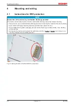
Page 28: ...ou are electrostatically discharged and avoid touching the contacts of the device directly Avoid contact with highly insulating materials synthetic fibers plastic film etc Surroundings working place p...

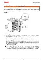
Page 29: ...oupler Join the compo nents with tongue and groove and push the terminals against the mounting rail until the lock clicks onto the mounting rail If the terminals are clipped onto the mounting rail fir...

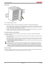
Page 30: ...ents The six spring contacts of the K Bus E Bus deal with the transfer of the data and the supply of the Bus Terminal electronics The power contacts deal with the supply for the field electronics and...

Page 31: ...ting or to damage on the terminal e g disruptive discharge to the PE line during insulation testing of a consumer with a nominal voltage of 230 V For insulation testing disconnect the PE supply line a...

Page 32: ...ies have been tried and tested for years They feature integrated screwless spring force technology for fast and simple assembly Pluggable wiring Fig 23 Pluggable wiring The terminals of KSxxxx and ESx...

Page 33: ...icularly compact design as the packaging density is twice as large as that of the standard 12 mm Bus Terminals Massive conductors and conductors with a wire end sleeve can be inserted directly into th...

Page 34: ...g the wire securely and per manently Terminal housing ELxxxx KLxxxx ESxxxx KSxxxx Wire size width 0 08 2 5 mm2 0 08 2 5 mm2 Wire stripping length 8 9 mm 9 10 mm High Density Terminals ELx8xx KLx8xx HD...

Page 35: ...Mounting and wiring EL3783 35 Version 1 1 Shielding Shielding Analog sensors and actors should always be connected with shielded twisted paired wires...

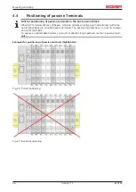
Page 36: ...not take an active part in data transfer within the bus terminal block are so called passive terminals The passive terminals have no current consump tion out of the E Bus To ensure an optimal data tra...

Page 37: ...cribed installation position requires the mounting rail to be installed horizontally and the connection surfaces of the EL KL terminals to face forward see Fig Recommended distances for standard insta...

Page 38: ...urrent If you do not connect the terminal point N with the neutral conductor of your mains supply e g if the EL3783 is used purely for current measurements terminal point N should be earthed in order...

Page 39: ...state mailbox and process data communication is possible IL1 OK green on Current IL1 ok IL1 Error red on Overcurrent on L1 Current 1 8 A with 1 A measuring range equivalent to 1 3 Arms Current 9 2 A...

Page 40: ...unting and wiring EL3783 40 Version 1 1 Fig 30 Measurement in a 3 phase 4 conductor grid asymmetrical load Fig 31 Measurement in a 3 phase 4 conductor grid with 3 voltage transformers asymmetrical loa...

Page 41: ...g 32 Measurement in a 3 phase 3 conductor grid asymmetrical load CAUTION Risk of device damage The user must ensure proper fusing of the voltage measurement path in accordance with the measured variab...

Page 42: ...em Manager I O Configuration In particular TwinCAT driver installation Fieldbus components Fieldbus Cards and Switches FC900x PCI Cards for Ethernet Installation Devices contain the terminals for the...

Page 43: ...d on the following sample configuration the subsequent subsections describe the procedure for TwinCAT 2 and TwinCAT 3 Control system PLC CX2040 including CX2100 0004 power supply unit Connected to the...

Page 44: ...004 and output EL2008 Note that all combinations of a configuration are possible for example the EL1004 terminal could also be connected after the coupler or the EL2008 terminal could additionally be...

Page 45: ...stem Manager displays the following user interface after startup Fig 35 Initial TwinCAT 2 user interface Generally TwinCAT can be used in local or remote mode Once the TwinCAT system including the use...

Page 46: ...shown in red perform a Broadcast Search if the exact computer name is not known enter the known computer IP or AmsNetID Fig 37 Specify the PLC for access by the TwinCAT System Manager selection of the...

Page 47: ...enu Actions Set Reset TwinCAT to Config Mode Shift F4 Fig 38 Select Scan Devices Confirm the warning message which follows and select EtherCAT in the dialog Fig 39 Automatic detection of I O devices s...

Page 48: ...u which then reads the elements present in the configuration below Fig 41 Reading of individual terminals connected to a device This functionality is useful if the actual configuration is modified at...

Page 49: ...ction Chart Editor CFC Sequential Function Chart SFC The following section refers to Structured Text ST After starting TwinCAT PLC Control the following user interface is shown for an initial project...

Page 50: ...cessful compilation TwinCAT PLC Control creates a tpy file in the directory in which the project was stored This file tpy contains variable assignments and is not known to the System Manager hence the...

Page 51: ...Manager The two variables bEL1004_Ch4 and nEL2008_value can now be assigned to certain process objects of the I O configuration Assigning variables Open a window for selecting a suitable process objec...

Page 52: ...aneously activate Continuous and All types Note that the Continuous checkbox was also activated This is designed to allocate the bits contained in the byte of the variable nEL2008_value sequentially t...

Page 53: ...ntext menu of a PDO can be executed in the other direction so that the respective PLC instance can then be selected Activation of the configuration The allocation of PDO to PLC variables has now estab...

Page 54: ...k the PLC with the real time system via menu option Online Login the F11 key or by clicking on the symbol The control program can then be loaded for execution This results in the message No program on...

Page 55: ...ronment areas available together with Microsoft Visual Studio after startup the project folder explorer appears on the left in the general window area cf TwinCAT System Manager of TwinCAT 2 for commun...

Page 56: ...user interface First create a new project via or under File New Project In the following dialog make the corresponding entries as required as shown in the diagram Fig 53 Create new TwinCAT project The...

Page 57: ...ed on the respective PLC TwinCAT can be used in local mode and thereby the next step is Insert Device 58 If the intention is to address the TwinCAT runtime environment installed on a PLC as developmen...

Page 58: ...n entered it is available for selection as follows a password may have to be entered After confirmation with OK the target system can be accessed via the Visual Studio shell Adding devices In the proj...

Page 59: ...be acknowledged Based on the sample configuration 43 described at the beginning of this section the result is as follows Fig 59 Mapping of the configuration in VS shell of the TwinCAT3 environment The...

Page 60: ...l supports all languages described in IEC 61131 3 There are two text based languages and three graphical languages Text based languages Instruction List IL Structured Text ST Graphical languages Funct...

Page 61: ...LC_example as project name for example and select a corresponding directory Fig 62 Specifying the name and directory for the PLC programming environment The Main program which already exists by select...

Page 62: ...Commissioning EL3783 62 Version 1 1 Fig 63 Initial Main program of the standard PLC project To continue sample variables and a sample program have now been created...

Page 63: ...r followed by the compile process Fig 65 Start program compilation The following variables identified in the ST PLC program with AT are then available in under Assignments in the project folder explor...

Page 64: ...on tree Fig 67 Selecting PDO of type BOOL According to the default setting certain PDO objects are now available for selection In this sample the input of channel 4 of the EL1004 terminal is selected...

Page 65: ...s can also be checked by selecting a Goto Link Variable from the context menu of a variable The object opposite in this case the PDO is automatically selected Fig 69 Application of a Goto Link variabl...

Page 66: ...he bottom right of the VS shell development environment The PLC system can then be started as described below Starting the controller Select the menu option PLC Login or click on to link the PLC with...

Page 67: ...io Integration Choice of the programming language Supports object orientated extension of IEC 61131 3 Usage of C C as programming language for real time applications Connection to MATLAB Simulink Open...

Page 68: ...he Install button A driver should only be installed on compatible devices A Windows warning regarding the unsigned driver can be ignored Alternatively an EtherCAT device can be inserted first of all a...

Page 69: ...plorer under I O After the installation the driver appears activated in the Windows overview for the network interface Windows Start System Properties Network Fig 75 Windows properties of the network...

Page 70: ...Commissioning EL3783 70 Version 1 1 Fig 77 Incorrect driver settings for the Ethernet port...

Page 71: ...here an EL6601 or similar devices are used it is useful to specify a fixed IP address for this port via the Internet Protocol TCP IP driver setting and to disable DHCP In this way the delay associated...

Page 72: ...was current at the time when the TwinCAT build was created For TwinCAT 2 11 TwinCAT 3 and higher the ESI directory can be updated from the System Manager if the programming PC is connected to the Int...

Page 73: ...on 1019 or for an older revision The ESI must then be requested from the manufacturer in this case Beckhoff b an ESI is present for the EL2521 0000 device but only in an older revision e g 1018 or 101...

Page 74: ...leted as follows close all System Manager windows restart TwinCAT in Config mode delete OnlineDescription0000 xml restart TwinCAT System Manager This file should not be visible after this procedure if...

Page 75: ...3783 75 Version 1 1 Reasons may include Structure of the xml does not correspond to the associated xsd file check your schematics Contents cannot be translated into a device description contact the fi...

Page 76: ...resence of the actual I O environment drives terminals EJ modules If the configuration is to be prepared in advance of the system configuration as a programming system e g on a laptop this is only pos...

Page 77: ...on 87 can also be carried out for comparison 5 1 2 5 OFFLINE configuration creation Creating the EtherCAT device Create an EtherCAT device in an empty System Manager window Fig 87 Append EtherCAT devi...

Page 78: ...can be appended by right clicking on a device in the configuration tree Fig 91 Appending EtherCAT devices left TwinCAT 2 right TwinCAT 3 The dialog for selecting a new device opens Only devices for w...

Page 79: ...ion can be displayed as Extended Information Fig 93 Display of device revision In many cases several device revisions were created for historic or functional reasons e g through technological advancem...

Page 80: ...This also enables subsequent replacement of devices without changing the configuration different specifications are possible for drives Example If an EL2521 0025 1018 is specified in the configuration...

Page 81: ...Commissioning EL3783 81 Version 1 1 Fig 96 EtherCAT terminal in the TwinCAT tree left TwinCAT 2 right TwinCAT 3...

Page 82: ...online search is not available in RUN mode production operation Note the differentiation be tween TwinCAT programming system and TwinCAT target system The TwinCAT 2 icon or TwinCAT 3 icon within the...

Page 83: ...e respective devices are lo cated in the stored ESI data and integrated in the configuration tree in the default state defined there Fig 101 Example default state NOTE Slave scanning in practice in se...

Page 84: ...iguration B tsm in order to check the built machine However if the series machine production department now doesn t use B tsm but instead carries out a scan to create the productive configuration the...

Page 85: ...hed to online state OPERATIONAL Fig 107 Config FreeRun query left TwinCAT 2 right TwinCAT 3 In Config FreeRun mode the System Manager display alternates between blue and red and the EtherCAT device co...

Page 86: ...ce is detected i e an EtherCAT slave for which no ESI XML description is available In this case the System Manager offers to read any ESI that may be stored in the device This case is described in the...

Page 87: ...uration is then replaced by the revision found this can affect the supported process data and functions If a scan is initiated for an existing configuration the actual I O environment may match the co...

Page 88: ...ed on the higher revision number Device selection based on revision compatibility The ESI description also defines the process image the communication type between master and slave device and the devi...

Page 89: ...offers a function Change to Compatible Type for the exchange of a device whilst retaining the links in the task Fig 116 Dialog Change to Compatible Type left TwinCAT 2 right TwinCAT 3 This function i...

Page 90: ...bs are now available for configuring the terminal And yet the dimension of complexity of a subscriber determines which tabs are provided Thus as illustrated in the example above the terminal EL3751 pr...

Page 91: ...the start up phase Tick the control box to the left of the input field in order to modify the default value Previous Port Name and port of the EtherCAT device to which this device is connected If it...

Page 92: ...difications include mask out a channel displaying additional cyclic information 16 bit display instead of 8 bit data size etc In so called intelligent EtherCAT devices the process data information is...

Page 93: ...incorrect configuration the EtherCAT slave usu ally refuses to start and change to OP state The System Manager displays an invalid SM cfg log ger message This error message invalid SM IN cfg or invali...

Page 94: ...nt to the mailbox Move Up This button moves the selected request up by one position in the list Move Down This button moves the selected request down by one position in the list New This button adds a...

Page 95: ...ect can be read but no data can be written to the object read only P An additional P identifies the object as a process data object Value Value of the object Update List The Update list button updates...

Page 96: ...cts included in the object list of the slave is uploaded from the slave via SDO information The list below can be used to specify which object types are to be uploaded Offline via EDS File If this opt...

Page 97: ...ain Current State Indicates the current state of the EtherCAT device Requested State Indicates the state requested for the EtherCAT device DLL Status Indicates the DLL status data link layer status of...

Page 98: ...t is deactivated not selected and greyed out this indicates that the input is excluded from the PDO assignment In order to be able to select a greyed out PDO the currently selected PDO has to be desel...

Page 99: ...riefly deals with a number of aspects of EtherCAT Slave operation under TwinCAT More detailed information on this may be found in the corresponding sections of for instance the EtherCAT System Documen...

Page 100: ...EtherCAT Master updated in every cycle red Output variables from the Slave to the EtherCAT Master updated in every cycle green Information variables for the EtherCAT Master that are updated acyclicall...

Page 101: ...on This may possibly have effects on the process data of other Slaves that are located in the same Syn cUnit In order for the higher level PLC task or cor responding control applications to be able to...

Page 102: ...ocally in the slave depends on the device EL terminals except the EL66xx are able to save in this way The user must manage the changes to the StartUp list Commissioning aid in the TwinCAT System Manag...

Page 103: ...operation After the operating power is switched on an EtherCAT Slave must go through the following statuses INIT PREOP SAFEOP OP to ensure sound operation The EtherCAT Master directs these statuses i...

Page 104: ...as standard EtherCAT Master OP Slaves OP This setting applies equally to all Slaves Fig 132 Default behaviour of the System Manager In addition the target state of any particular Slave can be set in...

Page 105: ...e Fig 134 PLC function blocks Note regarding E Bus current EL ES terminals are placed on the DIN rail at a coupler on the terminal strand A Bus Coupler can supply the EL terminals added to it with the...

Page 106: ...ove a warning message E Bus Power of Terminal is output in the logger window when such a configuration is activated Fig 136 Warning message for exceeding E Bus current NOTE Caution Malfunction possibl...

Page 107: ...document We reserve the right to modify the content of this docu ment at any time and accept no responsibility for errors and missing information Automatic current range switching The EL3783 features...

Page 108: ...temporary folder Fig 137 Opening the tnzip archive Select the tnzip file sample program A further selection window opens Select the destination directory for storing the project For a description of t...

Page 109: ...ck takes place as soon as the maximum values of a full half wave on all the current channels lie below the threshold value T_ 5A 1A of approx 1 69 A momentary DYN1 DYN2 DYN3 By default the terminal is...

Page 110: ...tables below show suitable rated grid voltages according to EN60664 1 2003 for the voltage measuring inputs of the EL3783 three phase 4 conductor grid with earthed protective conductor UL N UL L 66 V...

Page 111: ...analog or digital input device supplies not only one measured value for each process data cycle EtherCAT cycle duration T but several which are determined at a constant interval t T The ratio T t is...

Page 112: ...using the revision as below specified in the configuration the integrated ScopeView recognizes in its variable browser that the oversampling data is an array package and activates ForceOversampling a...

Page 113: ...iguration it will be illustrated how an oversampling variable can be represented by the Scope as a standard part of the TwinCAT 3 environment This will be explained by means of several steps based on...

Page 114: ...he indices can be set from 0 to 9 also As soon as the compiling procedure was started and ended successful in doing so no program code may be present the array appears into the solution explorer of th...

Page 115: ...ater on The task cycle time has to be changed if so Then with10 x Oversampling 1 ms at 100 s base time resulting 10 ticks will be set by the usage of the EL3751 for example Fig 144 Task property Creat...

Page 116: ...last preceding paragraph Step 2a or rather Var 1 according to the last preceding paragraph Step 2b within the Solution Explorer a window opens to select the process data Fig 146 Set up the link of th...

Page 117: ...on Axis A for selection of the scope features B Fig 148 Selection of the oversampling variable with the target browser By addressing the corresponding system that represents the PLC containing the arr...

Page 118: ...nt cycle time The X axis view was fitted properly by using Panning X after the recording was stopped Following the Chart property Use X Axis SubGrid was set to true with 10 divisions as well as the Ch...

Page 119: ...left sided solution explorer I O Devices Device EtherCAT Image Next the register card ADS have to be selected to activate each checkbox Enable ADS Server and Create symbols then the port entry is don...

Page 120: ...EtherCAT device Also see Beckhoff Information System 5 4 2 TwinCAT 2 procedure The TwinCAT Scope2 supports the import and display of oversampling process data such as is used by oversampling able ter...

Page 121: ...via ADS without further measures since PLC variables are always created as ADS symbols in the background Fig 154 PLC in the System Manager Note the Scope2 can only see such variables in the variable...

Page 122: ...stem Manager an instance of it can be assigned to an additional task with a right click It appears in the overview sorted according to bit size Fig 157 Overview of declared types In this example the v...

Page 123: ...task will not run automatically ADS symbol tables are then created for all variables that have this task in their process data images Fig 160 Settings in the additional task Step 2 Configuration in th...

Page 124: ...ForceOversampling and DataType INT16 must be set in the channel which has now been created If necessary SymbolBased must be temporarily deactivated in addition Fig 163 Channel settings In order to che...

Page 125: ...issioning EL3783 125 Version 1 1 Fig 164 Activation of the marks An additional example illustrates the following image by representation of an oversampling variable from the EL3751 with 10 x oversampl...

Page 126: ...activated due to the oversampling variable is not provided by the terminal box Proceeding with TwinCAT 2 alternatively via ADS In former TwinCAT 2 versions or a lower revision as specified in the tab...

Page 127: ...tion tree I O Configuration I O Devices Device EtherCAT Device Image Next the register card ADS have to be selected to activate each checkbox Enable ADS Server and Create symbols then the port entry i...

Page 128: ...rsampling record Beckhoff TwinCAT supports the Scope2 with some oversampling devices in a special way by automatically calculating a special ADS array symbol in the background which appears in the Sco...

Page 129: ...g related to the respective constant measuring range Output value presentation Voltage MBE 737 2575 V 130 400V Wurzel 2 22 5 mV digit Current 5 A range MBE 9 207527 130 5A root 2 281 A digit 1 A range...

Page 130: ...s data directly In order to transmit the limit information therefore define an input byte e g and link the limit with the VariableSizeMismatch dialog Additional task 2 bit variables can be created in...

Page 131: ...be changed in the CoE of the respective channel Fig 171 User settings and vendor calibration in the CoE online directory Changes in the CoE directory In case of changes to the CoE default parameters i...

Page 132: ...5 0x1A20 0x1A25 0x1A30 0x1A35 0x1A40 0x1A45 0x1A50 0x1A55 0x1A61 Synchronous with 8 fold oversampling Synchronous oversampling 16 0x1A00 0x1A07 0x1A10 0x1A17 0x1A20 0x1A27 0x1A30 0x1A37 0x1A40 0x1A47...

Page 133: ...EL3783 133 Version 1 1 Fig 172 EL3783 Selection dialog Predefined PDO Assignment Process image The EL3783 is inserted into the configuration by default with the 10 fold oversampling process image and...

Page 134: ...Commissioning EL3783 134 Version 1 1 Fig 173 Process image of the EL3783 in the TwinCAT System Manager In particular the EL3783 offers the following cyclic information...

Page 135: ...was determined The currently supplied set of 20 samples was started at the time 7 777 216 1 000 000 cycle time 6 777 216 ns The time interval between the samples is 1 000 000 20 50 000 ns Hence the 5t...

Page 136: ...on trigger and conversion time The EL3783 generally operates in oversampling mode It can be operated with and without Distributed Clocks activated Distributed Clocks activated the EtherCAT system wide...

Page 137: ...thus be used in systems that have no Distributed Clocks functionality The time accuracy of the measured values is reduced however The EtherCAT cycle time must be selected such that it is not less than...

Page 138: ...scription use CoE reload for resetting changes Introduction The CoE overview contains objects for different intended applications Objects required for parameterization during commissioning Restore obj...

Page 139: ...11 Current range 100 Measuring range 1 A no automatic switchover 500 Measuring range 5 A no automatic switchover 600 Dynamic 0 fast switching 601 Dynamic 1 602 Dynamic 2 603 Dynamic 3 inert switching...

Page 140: ...ted BOOLEAN RO FALSE Index 60p2 Samples for p 0 5 corresponding to channel 1 6 Index hex Name Meaning Data type Flags Default 60p2 0 Samples Maximum subindex UINT8 RO 100 60p2 01 Subindex 001 Sample 0...

Page 141: ...ge Index hex Name Meaning Data type Flags Default 6063 0 Sample Count Max subindex UINT8 RO 5 6063 01 High Current Range 1 Current range of the single sample 1 UINT16 RO 0x00 0 6063 02 High Current Ra...

Page 142: ...tage Current TxPDO Par Samples for Ch 1 Ch 6 01hex pp 5Fhex pp 10 20 30 40 50 Index hex Name Meaning Data type Flags Default 18pp 0 AI TxPDO Par Sample PDO Parameter TxPDO UINT8 RO 6 18pp 06 Exclude T...

Page 143: ...or Current Samples INT16 RO Index 1A60 AI TxPDO Map NextSyncTime Index hex Name Meaning Data type Flags Default 1A60 0 AI TxPDO Map NextSyncTime Max subindex UINT8 RO 1 1A60 01 Subindex 001 1 PDO Mapp...

Page 144: ...x05 High Current Range Active UINT32 RO 0x6063 05 1 1A63 06 Subindex 006 6 PDO Mapping entry object 0x6063 Current Range entry 0x00 Align UINT32 RO 0x0000 00 15 Index 1C00 0 Sync manager type Index he...

Page 145: ...ed TxPDO contains the index of the associ ated TxPDO mapping object UINT16 RW 0x1A26 6694dec 1C13 07 SubIndex 007 7 allocated TxPDO contains the index of the associ ated TxPDO mapping object UINT16 RW...

Page 146: ...RO 0x00000000 0dec 1C33 08 Command With this entry the real required process data provision time can be measured 0 Measurement of the local cycle time is stopped 1 Measurement of the local cycle time...

Page 147: ...RW 0x00000156 342dec Index F081 Download revision Index hex Name Meaning Data trype Flags Default F008 0 Download revision reserved UINT32 RW 0x00000000 0dec 5 7 Notices on analog specifications Beck...

Page 148: ...ains random and systematic portions of the referred device i e all influences such as temperature inherent noise aging etc It is always to be regarded as a positive negative span with even if it is sp...

Page 149: ...ror outside the basic accuracy at 23 C Due to the extensive uncertainty considerations that are incorporated in the determination of the basic accuracy at 23 C Beckhoff recommends a quadratic summatio...

Page 150: ...en two potential points For voltage measurements a large R is used in order to ensure a high impedance For current measurements a small R is used as shunt If the purpose is resistance measurement corr...

Page 151: ...portant to pay attention to the quality of this potential noiselessness voltage stability At this GND point a wire may be connected to make sure that VCM max is not exceeded in the differential sensor...

Page 152: ...ufactured on the application side to be connected with the right polarity to Signal and Signal It is important to refer to the information page Configuration of 0 4 20 mA differential inputs see docum...

Page 153: ...and related product groups exactly the same Differential EL3x1x 0 20 mA EL3x2x 4 20 mA KL and related product groups exactly the same Preferred current direction because of internal diode Preferred cu...

Page 154: ...Commissioning EL3783 154 Version 1 1 Single ended Differential Fig 182 2 3 and 4 wire connection at single ended and differential inputs...

Page 155: ...der consideration For multi channel terminals boxes with resistive direct ohmic galvanic or capacitive connection between the channels the reference ground should preferably be the symmetry point of a...

Page 156: ...user perspective they all have a common characteristic after the conversion a certain digital value is available in the controller for further processing This digital value the so called analog proces...

Page 157: ...hronous or more quickly if the AI channel operates in slow FreeRun mode or more slowly e g with oversampling is then a question of the fieldbus setting and which modes the AI device supports For Ether...

Page 158: ...awtooth or sine A simultaneous square wave signal would be used as reference The signal delay ms s is then the interval between the applied electrical signal with a particular amplitude and the moment...

Page 159: ...Commissioning EL3783 159 Version 1 1 Actual sampling rate of the ADC if different from the channel sampling rate Time correction values for run times with different filter settings etc...

Page 160: ...e can store up to 250 DiagMessages in its own CoE Each DiagMessage consists of Diag Code 4 byte Flags 2 byte info warning or error Text ID 2 byte reference to explanatory text from the ESI XML Timesta...

Page 161: ...logger Since TwinCAT 3 1 build 4022 DiagMessages send by the terminal are shown by the TwinCAT ADS Logger Given that DiagMessages are represented IO comprehensive at one place commissioning will be si...

Page 162: ...the case of Beckhoff EtherCAT devices EL EP it usually reads according to xyzz x y zz 0 Systeminfo 2 reserved 1 Info 4 Warning 8 Error 0 System 1 General 2 Communication 3 Encoder 4 Drive 5 Inputs 6 I...

Page 163: ...deleted Idx 0x X SubIdx 0x X Data deleted 0x117F Information General Information 0x X 0x X 0x X Information 0x1201 Information Communication Communication re es tablished Communication to the field si...

Page 164: ...n 0x2004 Information System s valid IP Configura tion IP d d d d assigned by Dhcp server d d d d Valid IP configuration assigned by the DHCP server 0x2005 Information System s Dhcp client timed out DH...

Page 165: ...the PDO Configuration The selected PDOs do not match the set operating mode Sample Drive operates in velocity mode but the ve locity PDO is but not mapped in the PDOs 0x417F Warning General Warning 0x...

Page 166: ...ive Limit Current Limit current is limited 0x4419 Warning Drive Limit Amplifier I2T model exceeds 100 The threshold values for the maximum current were exceeded 0x441A Warning Drive Limit Motor I2T mo...

Page 167: ...Communication between the fieldbus and the output stage is secured by a Watchdog The axis is stopped automatically if the fieldbus communication is inter rupted The EtherCAT connection was interrupted...

Page 168: ...00 Error Drive Incorrect drive configura tion 0x X d Drive incorrectly configured 0x8401 Error Drive Limiting of calibration ve locity d d Limitation of the calibration velocity 0x8402 Error Drive Eme...

Page 169: ...e not in the correct range 0x8611 Error General IO Output voltage to low Output voltage too low 0x8612 Error General IO Output voltage to high Output voltage too high 0x8613 Error General IO Over curr...

Page 170: ...t up for this purpose Generally the slave does not check whether the new data are suitable i e it may no longer be able to operate if the data are unsuitable Simplified update by bundle firmware The u...

Page 171: ...vision 0016 The configured identifier must be compatible with the actual device description used as hardware i e the description which the slave has loaded on start up in this case EL3204 Normally the...

Page 172: ...uration is identical otherwise a change dialog appears for entering the actual data in the configuration Fig 193 Change dialog In this example in Fig Change dialog an EL3201 0000 0017 was found while...

Page 173: ...d in the following dialog see Fig Selecting the new ESI The checkbox Show Hidden Devices also displays older normally hidden versions of a slave Fig 195 Selecting the new ESI A progress bar in the Sys...

Page 174: ...terminal 2 EL3204 and select the tab CoE Online CAN over EtherCAT CoE Online and Offline CoE Two CoE directories are available online This is offered in the EtherCAT slave by the controller if the Eth...

Page 175: ...ring a firmware update Switch to the Online tab to update the controller firmware of a slave see Fig Firmware Update Fig 197 Firmware Update Proceed as follows unless instructed otherwise by Beckhoff...

Page 176: ...date may be accomplished via an rbf file Controller firmware for processing I O signals FPGA firmware for EtherCAT communication only for terminals with FPGA The firmware version number included in th...

Page 177: ...right click the table header and select Properties in the context menu Fig 199 Context menu Properties The Advanced Settings dialog appears where the columns to be displayed can be selected Under Dia...

Page 178: ...terminal must have FPGA firmware version 10 or higher Older firmware versions can only be updated by the manufacturer Updating an EtherCAT device The following sequence order have to be met if no othe...

Page 179: ...nager select the terminal for which the FPGA firmware is to be updated in the example Terminal 5 EL5001 and click the Advanced Settings button in the EtherCAT tab The Advanced Settings dialog appears...

Page 180: ...the device A download of firmware to an EtherCAT device must not be interrupted in any case If you interrupt this process by switching off power supply or disconnecting the Ethernet link the EtherCAT...

Page 181: ...ke sure that the firmware is suit able for the hardware version EL3783 Hardware HW Firmware FW Revision no Release date 00 01 01 EL3783 0000 0016 2016 02 02 2016 04 02 03 03 2016 10 04 05 2017 02 06 E...

Page 182: ...he delivery state Fig 203 Entering a restore value in the Set Value dialog Alternative restore value In some older terminals the backup objects can be switched with an alternative restore value Deci m...

Page 183: ...5246 963 0 Fax 49 0 5246 963 198 e mail info beckhoff com Beckhoff Support Support offers you comprehensive technical assistance helping you not only with the application of individual Beckhoff produc...

Page 184: ...r 24 Fig 16 Offline list 25 Fig 17 Online list 25 Fig 18 Spring contacts of the Beckhoff I O components 28 Fig 19 Attaching on mounting rail 29 Fig 20 Disassembling of terminal 30 Fig 21 Power contact...

Page 185: ...C programming environment 61 Fig 63 Initial Main program of the standard PLC project 62 Fig 64 Sample program with variables after a compile process without variable integration 63 Fig 65 Start progra...

Page 186: ...cified EtherCAT device left TwinCAT 2 right TwinCAT 3 85 Fig 106 Scan progressexemplary by TwinCAT 2 85 Fig 107 Config FreeRun query left TwinCAT 2 right TwinCAT 3 85 Fig 108 Displaying of Free Run an...

Page 187: ...nding the variable aUI_Samples below axis within the scope project of the solution explorer 117 Fig 150 Example of recording a sine signal with 10 x oversampling at 1 ms measurement cycle time 118 Fig...

Page 188: ...ram signal delay step response 158 Fig 187 Diagram signal delay linear 158 Fig 188 DiagMessages in the CoE 160 Fig 189 Implementation of the DiagMessage system in the TwinCAT System Manager 161 Fig 19...

Reviews: