


Mounting and wiring
EL3773
30
Version: 2.5
Assembly
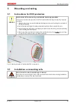
Fig. 19: Attaching on mounting rail
The Bus Coupler and Bus Terminals are attached to commercially available 35 mm mounting rails (DIN rails
according to EN 60715) by applying slight pressure:
1. First attach the Fieldbus Coupler to the mounting rail.
2. The Bus Terminals are now attached on the right-hand side of the Fieldbus Coupler. Join the compo-
nents with tongue and groove and push the terminals against the mounting rail, until the lock clicks
onto the mounting rail.
If the Terminals are clipped onto the mounting rail first and then pushed together without tongue and
groove, the connection will not be operational! When correctly assembled, no significant gap should
be visible between the housings.
Note
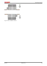
Fixing of mounting rails
The locking mechanism of the terminals and couplers extends to the profile of the mounting
rail. At the installation, the locking mechanism of the components must not come into con-
flict with the fixing bolts of the mounting rail. To mount the mounting rails with a height of
7.5 mm under the terminals and couplers, you should use flat mounting connections (e.g.
countersunk screws or blind rivets).
Summary of Contents for EL3773
Page 1: ...Documentation EL3773 Power Monitoring Oversampling Terminal 2 5 2018 03 13 Version Date...
Page 2: ......
Page 6: ...Table of contents EL3773 6 Version 2 5...
Page 39: ...Mounting and wiring EL3773 39 Version 2 5 Fig 29 Other installation positions...
Page 41: ...Mounting and wiring EL3773 41 Version 2 5 Fig 31 Block diagram...
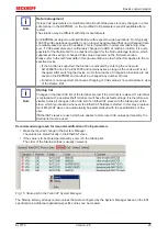
Page 47: ...Commissioning EL3773 47 Version 2 5 Fig 38 Incorrect driver settings for the Ethernet port...
Page 147: ...Commissioning EL3773 147 Version 2 5 Fig 168 Confirming program start...


