


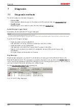


Diagnosis
EL3773
151
Version: 2.5
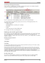
TwinCAT System Manager implementation
From TwinCAT 2.11 DiagMessages, if available, are displayed in the device’s own interface. Operation
(collection, confirmation) also takes place via this interface.
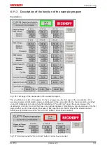
Fig. 173: Implementation of the DiagMessage system in the TwinCAT System Manager
The operating buttons (B) and the history read out (C) can be seen on the Diag History tab (A). The
components of the message:
• Info/Warning/Error
• Acknowledge flag (N = unconfirmed, Q = confirmed)
• Time stamp
• Text ID
• Plain text message according to ESI/XML data
The meanings of the buttons are self-explanatory.
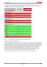
DiagMessages within the ADS Logger/Eventlogger
Since TwinCAT 3.1 build 4022 DiagMessages send by the terminal are shown by the TwinCAT ADS Logger.
Given that DiagMessages are represented IO- comprehensive at one place, commissioning will be
simplified. In addition, the logger output could be stored into a data file – hence DiagMessages are available
long-term for analysis.
Reading messages into the PLC
- In preparation -
Interpretation
Time stamp
The time stamp is obtained from the local clock of the terminal at the time of the event. The time is usually
the distributed clock time (DC) from register x910.
Please note: When EtherCAT is started, the DC time in the reference clock is set to the same time as the
local IPC/TwinCAT time. From this moment the DC time may differ from the IPC time, since the IPC time is
not adjusted. Significant time differences may develop after several weeks of operation without a EtherCAT
restart. As a remedy, external synchronization of the DC time can be used, or a manual correction
calculation can be applied, as required: The current DC time can be determined via the EtherCAT master or
from register x901 of the DC slave.
Structure of the Text ID
The structure of the MessageID is not subject to any standardization and can be supplier-specifically
defined. In the case of Beckhoff EtherCAT devices (EL, EP) it usually reads according to
xyzz
:
Summary of Contents for EL3773
Page 1: ...Documentation EL3773 Power Monitoring Oversampling Terminal 2 5 2018 03 13 Version Date...
Page 2: ......
Page 6: ...Table of contents EL3773 6 Version 2 5...
Page 39: ...Mounting and wiring EL3773 39 Version 2 5 Fig 29 Other installation positions...
Page 41: ...Mounting and wiring EL3773 41 Version 2 5 Fig 31 Block diagram...
Page 47: ...Commissioning EL3773 47 Version 2 5 Fig 38 Incorrect driver settings for the Ethernet port...
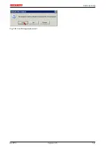
Page 147: ...Commissioning EL3773 147 Version 2 5 Fig 168 Confirming program start...


